Anyone know how to make resistors and capacitors etc? Looking for a way to cut costs and get individual pieces (or just individual pieces if it's going to be worth the cost)
i found a DIY article from the 1920's about DIYing electrolytic caps with aluminum foil, blotter paper and a simple electrolyte formula, but i can't find the link where i got it....
electrolytic capacitors are a derivative of the early 20th century "electrolytic rectifier"
a description of how they are formed can be found here:
http://www.faradnet.com/deeley/chapt_02.htm
i don't know how to find the 1920's article... i have a pdf of it somewhere here... maybe i can upload it to the Radio Experimenter yahoo group
i also found this web page:
http://home.earthlink.net/~lenyr/borax.htm
The now famous Duelund caps were created that way
He got the raw materials from Jensen
You can make resistors, with resistor wire wound on wood
But Im not sure its very reliable
He got the raw materials from Jensen
You can make resistors, with resistor wire wound on wood
But Im not sure its very reliable
Somewhere, I have an article from "Wireless World" c1955? which describes how to make your own transistors from a couple of diodes.
I will post it if/when I find it.
Andy
I will post it if/when I find it.
Andy
poynton said:Somewhere, I have an article from "Wireless World" c1955? which describes how to make your own transistors from a couple of diodes.
I will post it if/when I find it.
Andy
I hope you are joking, right?
Check the article's date!
I buy my 1% metal film 600mW resistors from Rapid by the hundred @ ~£1.50/100
Many of their capacitors are also cheap.
My PSU caps were imported from the USA. A couple of Farads in stock
Ask Rapid for a catalogue and use their Rapidonline.com internet service.
Add Farnell, Cricklewood, RS, to your sellers list.
Many of their capacitors are also cheap.
My PSU caps were imported from the USA. A couple of Farads in stock
Ask Rapid for a catalogue and use their Rapidonline.com internet service.
Add Farnell, Cricklewood, RS, to your sellers list.
making one's own components can be a great learning experience. actually to make a transistor, you would need a crystal detector and two catwhiskers. there has to be a common piece of semiconductor for C-E current to flow. of course such a transistor would be extremely limited in it's voltage and current ratings. i've made resistors from carbon fiber and from the black antistatic foam that ICs sometimes come in. there's also ways to make capacitors from aluminum foil and a variety of dielectrics, such as plastic wrap, waxed paper, etc...
i wouldn't use these components in an amplifier, since their voltage and temperature characteristics are somewhat unpredictable, but they are good learning tools....
i wouldn't use these components in an amplifier, since their voltage and temperature characteristics are somewhat unpredictable, but they are good learning tools....
I tried rolling my own small (1nF) PIO caps. Got pretty consistent at it too 🙂
Now, the temprature stability of them.... meh 🙁
Cheers!
Now, the temprature stability of them.... meh 🙁
Cheers!
It isn't difficult to make low value wire wound resistors of high quality. High values are much more difficult. It's a bit harder to wind film caps, but it can be done. Not sure if I'd trust a homebrew electrolytic. Transistors with decent specifications aren't practical, but there's a video of a guy that makes tubes (in France?) on the net somewhere. And you can certainly wind transformers. When all is said and done, you'll spend far more than if you just bought the parts.
Conrad Hoffman said:When all is said and done, you'll spend far more than if you just bought the parts.
Agreed.
But the experience is great. Why do you? Because you can! 1/2 the great inventions were done that way.
Conrad makes an interesting point mentioning transformers though. Those CAN be worthwhile....
1) A one-shot transformer for a project
2) Special design: interleave or impedance, current or funny voltage breakdown.
3) Unique characteristics (SMPS or other pulse transformers)
4) Reclaiming "dead" iron (open or shorted), or rewinding for other uses... like turning all these common as dirt 9V clock radio transformers into 6.3V filament ones (90% of my handwinds fall into this)
Cheers!
cliffforrest said:
I hope you are joking, right?
Check the article's date!
unclejed613 said:making one's own components can be a great learning experience. actually to make a transistor, you would need a crystal detector and two catwhiskers. there has to be a common piece of semiconductor for C-E current to flow. of course such a transistor would be extremely limited in it's voltage and current ratings...........................
Funny....I posted a reply along these lines yesterday. Where did it go ?
The article was from the early '50s and gave quite detailed instructions to make a working transistor from 2 point contact germanium diodes. The germanium chunk from 1 formed the base and the 2 cats whiskers formed the emitter and collector, all held together using lab clamps and luck...very Heath-Robinson but it worked as an amplifier using 6v for a crystal set radio.
Andy
I was cynically sceptical on remembering observing, many many years ago, a techie inserting 2 diodes (of the 1N4148 variety) into a Curve Tracer socket and wondering why he could not get some Ic/Vce curves displayed ....
i was recently reading an article about memristors (the 4th passive component) and they mentioned in the article that Shockley's point contact transistor actually functioned more like a JFET, and i can see how that would happen....
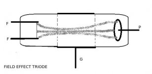
there was a tube made back in the 1920's called a "field effect" triode where the filament was at one end, the anode at the other end, and the "grid" was a band of conductive material around the outside of the center of the tube (on the outside of the glass). the electric field produced on the grid had enough influence on the current inside the tube that it was a working triode, but without the problem of grid current flowing when the grid was positive. that's another pdf file i have floating around here on one of my computers. it would be interesting to experiment with a device like that.....
yeah i tried the dual 1N4148 idea when i was about 10 yrs old, but i think i figured out real quick after looking a second time at how a transistor operates, why it didn't work.
field effect triode:
the grid is a conductive band on the outside of the glass and works much like the gate of a mosfet. with enough negative bias, it will pinch off the electron beam, and although it wasn't mentioned in the article i read, i suspect it might diverge the beam until it makes contact with the glass, with enough positive bias (although this might also be a much higher voltage than is on the plate). i don't know why this tube didn't survive the 20's and 30's, except that i must have hadlower gain than the standard "grid in the electron path" tube, and the "grid" was more susceptible to problems with humidity and external capacitances.
the grid is a conductive band on the outside of the glass and works much like the gate of a mosfet. with enough negative bias, it will pinch off the electron beam, and although it wasn't mentioned in the article i read, i suspect it might diverge the beam until it makes contact with the glass, with enough positive bias (although this might also be a much higher voltage than is on the plate). i don't know why this tube didn't survive the 20's and 30's, except that i must have hadlower gain than the standard "grid in the electron path" tube, and the "grid" was more susceptible to problems with humidity and external capacitances.
Attachments
Hello,
I don't know how to make passive components from my desk but i got the link of French maiden tube :
http://www.dailymotion.com/video/x3wrzo_fabrication-dune-lampe-triode_tech
I don't know how to make passive components from my desk but i got the link of French maiden tube :
http://www.dailymotion.com/video/x3wrzo_fabrication-dune-lampe-triode_tech
You legends! I wonder how hard it would be to tailor make valves, suppose it's just experience and experimenting
i have an early RCA book on how to design tubes..... interesting reading, but i don't have the equipment and materials. some of the materials would be pricey and any startup trying to make tubes would probably be hammered with hazmat regs these days....
i dream of this
Make: Online : Make your own vacuum tubes?
my hobbies are glass blowing (bongs) vintage electronics, and metal work (artwork)
someday perhaps i think i will start with a light bulb....
if the top link was interesting here is a diy
http://www.teralab.co.uk/Glass_Blowing/Introduction/Introduction_Page1.htm
Last edited:
- Status
- Not open for further replies.
- Home
- Design & Build
- Parts
- Anyone know how to make your own components?