This was a design I worked on last year, and some changes in what I want to do make it fairly useless to me at this point in time. I'd hold on to it, but honestly it is just recycled textbook filters (at least, I hope so lol) put together in one package.
I haven't had these boards printed, so obviously I haven't had the chance to bench test for errors. To implement the board as I had intended, there are still a few things that need to be done. The biggest is that the design requires ganged parallel potentiometers... quite a few. I had investigated the design of Tawaiinese Alpha pots, had ordered a batch to take apart, and had concluded that with a little patience and machining skill one could assemble a group of as many ganged pots as required - a ten gang is the max required here. The circuit includes spaces for multiturn precision trim pots so that each member of the large gang could be trimmed for end bias, so that at least the error could be grouped around some nominal value where accuracy is most important. An alternative is a gang of digital pots, but I wasn't wanting to go that route. See the functions below - if you wanted to, you could split up the 10-gang into smaller groups, but I didn't want to have to ear or instrument match crossover points between channels, high/low, etc. One knob to do it all, IMO.
The other thing that would need to be done is that as designed all the pots and switches were to be mounted on a secondary PCB, using a ribbon connector to make all connections back to the main board. That is much less of a challenge - something I just didn't get around to doing.
Anyway, here is a short description of the functional parts of the board design:
- Power supply for all filter sections, taking 120V in
- Auto sensing on (signal sensing), defeatable (hard on/off or auto)
- Stereo balanced inputs (accepts unbalanced)
- Stereo balanced outputs (accepts unbalanced)
- Integrated Linkwitz transform, defeatable, values can be adjusted to suit sub design
- Integrated room-gain adjustment, essentially a continuously adjustable high pass filter 6dB slope centered from ~10Hz to ~100Hz, defeatable
- RFI filtering on inputs
- High-pass outputs selectable 12/24dB/oct LR slopes, center frequency continuously variable
- Low-pass outputs selectable 0/12/24dB/oct LR slopes, center frequency continuously variable
- Both high pass and low pass, for both channels, center frequency set with one ganged set of pots (see above)
- 0-180 continuously adjustable all-pass phase setting on low-pass output, defeatble
- Output gains for high and low pass outputs
- Outputs balanced, high and low pass (can use with unbalanced)
It takes quite a few various switches and pots to make it all work, but I have a parts list for all of these (as well as for all other circuit components).
The idea was to have a flexible sub filter that could be used to match practically any main speakers and/or room. Small sealed mains? Use 24dB/oct on high pass an octave above F3 or 12dB/oct highpass centered at F3 along with a matching 24dB/oct lowpass for symmetric LR slopes. Or, alternatively for the same mains, opt for no high pass filtering of mains and use a 12dB/oct lowpass centered on their F3.
Ported mains? Probably a 24dB/oct highpass an octave above the F3 with matching 24dB/oct lowpass. Or, if desired, nothing on the highpass and a 24dB/oct lowpass at the mains' F3.
The design was intended to work with any combination of preamps without crossovers, pre/pro's with 12 or 24dB crossovers, sealed, ported, or even dipolar mains. The room gain allows one to use the Linwitz transform for anechoic flat, and then adjust for room gain depending on the size of room you have. This prevents you from having to make guesses about what room the sub may be in througout its life during the crossover design process.
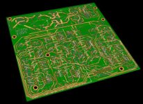
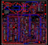
Here are some oldish snapshots of the layout...
I haven't had these boards printed, so obviously I haven't had the chance to bench test for errors. To implement the board as I had intended, there are still a few things that need to be done. The biggest is that the design requires ganged parallel potentiometers... quite a few. I had investigated the design of Tawaiinese Alpha pots, had ordered a batch to take apart, and had concluded that with a little patience and machining skill one could assemble a group of as many ganged pots as required - a ten gang is the max required here. The circuit includes spaces for multiturn precision trim pots so that each member of the large gang could be trimmed for end bias, so that at least the error could be grouped around some nominal value where accuracy is most important. An alternative is a gang of digital pots, but I wasn't wanting to go that route. See the functions below - if you wanted to, you could split up the 10-gang into smaller groups, but I didn't want to have to ear or instrument match crossover points between channels, high/low, etc. One knob to do it all, IMO.
The other thing that would need to be done is that as designed all the pots and switches were to be mounted on a secondary PCB, using a ribbon connector to make all connections back to the main board. That is much less of a challenge - something I just didn't get around to doing.
Anyway, here is a short description of the functional parts of the board design:
- Power supply for all filter sections, taking 120V in
- Auto sensing on (signal sensing), defeatable (hard on/off or auto)
- Stereo balanced inputs (accepts unbalanced)
- Stereo balanced outputs (accepts unbalanced)
- Integrated Linkwitz transform, defeatable, values can be adjusted to suit sub design
- Integrated room-gain adjustment, essentially a continuously adjustable high pass filter 6dB slope centered from ~10Hz to ~100Hz, defeatable
- RFI filtering on inputs
- High-pass outputs selectable 12/24dB/oct LR slopes, center frequency continuously variable
- Low-pass outputs selectable 0/12/24dB/oct LR slopes, center frequency continuously variable
- Both high pass and low pass, for both channels, center frequency set with one ganged set of pots (see above)
- 0-180 continuously adjustable all-pass phase setting on low-pass output, defeatble
- Output gains for high and low pass outputs
- Outputs balanced, high and low pass (can use with unbalanced)
It takes quite a few various switches and pots to make it all work, but I have a parts list for all of these (as well as for all other circuit components).
The idea was to have a flexible sub filter that could be used to match practically any main speakers and/or room. Small sealed mains? Use 24dB/oct on high pass an octave above F3 or 12dB/oct highpass centered at F3 along with a matching 24dB/oct lowpass for symmetric LR slopes. Or, alternatively for the same mains, opt for no high pass filtering of mains and use a 12dB/oct lowpass centered on their F3.
Ported mains? Probably a 24dB/oct highpass an octave above the F3 with matching 24dB/oct lowpass. Or, if desired, nothing on the highpass and a 24dB/oct lowpass at the mains' F3.
The design was intended to work with any combination of preamps without crossovers, pre/pro's with 12 or 24dB crossovers, sealed, ported, or even dipolar mains. The room gain allows one to use the Linwitz transform for anechoic flat, and then adjust for room gain depending on the size of room you have. This prevents you from having to make guesses about what room the sub may be in througout its life during the crossover design process.
Here are some oldish snapshots of the layout...
Attachments
Oh, and I should have probably been a little clearer in that I'm not trying to sell this or anything. Just putting it out there in case anyone wants to play around with it. Since I never took it to fabrication, it would be interesting to see how the design actually works out.
I'd be happy to post the files (from PCB123... a decent free routing program, and a pretty good place to order PCB's), parts list, block diagram, etc.
It would be nice if it worked out that someone could provide a solution for the multiganged pots, either analog or digital, for others to use. And someone a lot better than me would need to check the design, whether from the schematic or actual bench testing to debug.
It's been a while since I worked on this so it isn't that fresh in my memory, but I'd be happy to answer any questions about it.
erm, that one might be a little tricky. Most of the functional blocks were designed independently. They were brought together in PCB123 to produce a complete schematic to prepare for layout. PCB123's schematic layout looks like an absolute mess, and I doubt I could get a capture of it that would be at all helpful.
I've attached a PDF of the block diagram of the schematic. If you're really interested, the best thing is probably for me to send the actual PCB123 file, and for you to examine it in that program.
edit: crap, the pdf is too big to attach.
I've attached a PDF of the block diagram of the schematic. If you're really interested, the best thing is probably for me to send the actual PCB123 file, and for you to examine it in that program.
edit: crap, the pdf is too big to attach.
- Status
- Not open for further replies.
- Home
- Loudspeakers
- Subwoofers
- Anyone interested in what might be a nice active filter design?