I'm chasing a 60 cycle hum with a DMM which is obviously not going to work. Anyone in the greater Los Angeles area who might not charge too much just to tell me where the culprits may be in the circuit.
This is a super simple preamp with hardly any components so its not intense like a complex circuit or PCB.
PSU is in one box. Amp in another. Its my design not a commercial piece.
This is a super simple preamp with hardly any components so its not intense like a complex circuit or PCB.
PSU is in one box. Amp in another. Its my design not a commercial piece.
Would you share a schematic and a diagram of the connections between the supply and amp? You may find the help you need right here in this forum if you ask the right questions...
My first question: Are you sure it's 60 Hz hum? Could it be 120 Hz? Does your DMM measure frequency? Is it able to measure the frequency of the hum?
60 Hz is nearly always caused by a ground loop. Other causes include inductive and/or capacitive pick-up.
Is the hum present at all levels of the volume control? Does it vary when you adjust the volume control? If so, the hum comes in before the volume control.
Is the hum present in both channels or just one? What happens if you pull the tubes associated with one channel and disconnect its signal input and output cables?
~Tom
Hi Tom. I had several threads about this and the conclusion was need a scope.
Hum is the same at all levels. Identical in both channels.
I have the top Extech EX570meter It does have Hz setting.
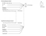
Two box preamp amp. PSU in one. Here's grounding and PSU schematic.
Hum is the same at all levels. Identical in both channels.
I have the top Extech EX570meter It does have Hz setting.
Two box preamp amp. PSU in one. Here's grounding and PSU schematic.
Attachments
I'm in OC (south county) and have a scope....no problem if you want to stop by......where are you located?
I'm Santa Monica. Thanks Boywonder for the offer! SFV would be much closer, though. Bob would you be up for it? You can PM if you want or email me.
What are you using for the heater on the triode? AC? DC? If you're using AC, I'd expect some residual hum. DC should be quiet.
What's the bias current in the triode? (Measure voltage across the 120 ohm resistor).
What's the frequency of the hum on the output? You say 60 Hz. Have you measured 60 Hz or are you relying on your hearing to determine the frequency?
Also, measure the AC voltage (yes AC voltage) on the B+ with the DMM. That will give you an idea of what the ripple voltage is. I don't know your setup, but in my 300B power amp, I can hear hum in the speaker when the ripple voltage gets above a few 100 mV. My speakers are 87 dB/W*m efficient.
I honestly don't think you'll get much out of poking around in the amp with a scope. I've looked at a few of your threads, and I think participated in some of them as well. But generally, I've found them lacking in detail as far as a problem description and measured data go. That said, I've probably missed the one thread that has everything in it... 🙂
How bad is the hum? Can you tell from the listening position? What power amp are you using?
How is the rest of the system connected? Speaking of.... Did you try my suggestion in Post 2 and disconnected one channel? What happened? The reason I'm asking is that I cured a ground loop by disconnecting the input cable for one channel. This exposed the fact that there was a ground loop and I could then focus on finding said ground loop.
~Tom
Last edited:
DC. Heater ripple is .004vac so no problem there. Bias is 12mA Plate has 200VDC.
Relying on hearing. I know what 120Hz sounds like its not that. Right, B+ has too much ripple. .3vac On the wood board with my hybrid choke/regulated supply I had it down to .045vac. Different circuit though and the regulated supply handled the ripple.
I have 96dB speakers. You can hear it from the listening position. Not when the music is on but in the quiet sections it bleeds through. Its not overpoweringly loud but noticeable enough to ruin the experience. Unless the music doesn't have any quiet sections 🙂
I think you did help in some of the threads. The first long one should've had all the measurements.
I have tried that in the past and no difference. - your comment in post 2 -- remember this is pure dual mono with separate ground planes for each channel.
Last edited:
Appears I'm still looking for someone in the Los Angeles area. It would be great to meet another DIY Audiophile plus this pre-amp is really sounding special and would be nice to hear.
I'm sure I could return the favor in other ways. 🙂
I'm sure I could return the favor in other ways. 🙂
It may be helpfull to use a current proble to find this noise...
Also a 1x voltage probe would also work provided you have an LNA on the front end of the scope would be needed to see anything small...
You can also find the source of noise by putting small resistance in series with the local AC current loops in the circuit....when the noise increases...you found the source loop....
Chris
Interesting. Unfortunately I do not have a scope. I'm not clear on your last sentence. Is this also with use of a scope?
Relying on hearing. I know what 120Hz sounds like its not that.
I'd prefer a measurement by a frequency counter or spectrum analyser. Many people these days use computer sound cards for spec an's...
I have 96dB speakers.
Well, there's your problem... 🙂 Any wiggle in the output voltage of the amp will be reproduced as audible sound by those speakers. That 300 mV ripple on the supply definitely has to go.
Have you tried increasing the capacitance in the supply filter? The one after the choke that is.
Not when the music is on but in the quiet sections it bleeds through.
That does not surprise me.
I have tried that in the past and no difference. - your comment in post 2 -- remember this is pure dual mono with separate ground planes for each channel.
Separate grounds. Separate supplies too? Or just one supply?
If it's two completely separate circuits, it should be trivial to power one side down and unplug it. That would eliminate any ground loops between the channels for sure.
How much AC is present on the amp output with the inputs grounded?
~Tom
Pharod... I noticed your reply in the other thread. So you are confident it's 60 Hz and not 120/180 Hz. Adding 180 uF to the supply cap (in parallel with the 40+60 uF that's already there) had no effect. Heaters are powered by DC.
That says ground loop to me.
It sounds like you have a regulated supply in your lab. I suggest that you pull the rectifier tube in the amp and feed the amp DC from the regulated supply. If that cures the hum, you have a coupling issue between the supply and the rest of the circuit. This coupling could come from the filter choke -- though I'd expect it to be 120 Hz in that case.
If it's not a supply issue, then it's either a loose connection (floating ground) or a ground loop. Those are my bets anyway.
If you're running dual mono, I would unplug one channel completely. Take it out of the chain to make 110 % sure you do not have a ground loop between the source, preamp, and power amp. Believe me. I've been there.
~Tom
Tom thanks for all the thinking on my problem. Yes, dual mono separate supplies. The regulated supply is now torn down.
Both ground rails have perfect continuity in the signal box back to the psu star ground. I'll try disconnecting one channel. I just don't know what the 180uF didn't result in any smoothing ie decreasing the ac ripple. I tried it twice.
Both ground rails have perfect continuity in the signal box back to the psu star ground. I'll try disconnecting one channel. I just don't know what the 180uF didn't result in any smoothing ie decreasing the ac ripple. I tried it twice.
A friend in Europe got back to me and suggested doing what I do on the heater out - pseudo center tap from the middle of two resistors across the 5AR4 heaters.
I made up a 1/2W pair but they got so hot they fried. Since this is AC I don't know. I've never tried this with AC before. I thought I would try it on C2 but that just stopped the DC B+ power from ramping up and also started to burn the resistors.
I made up a 1/2W pair but they got so hot they fried. Since this is AC I don't know. I've never tried this with AC before. I thought I would try it on C2 but that just stopped the DC B+ power from ramping up and also started to burn the resistors.
I just don't know what the 180uF didn't result in any smoothing ie decreasing the ac ripple. I tried it twice.
That is weird. I assume you measured the AC with your DMM. That should be OK, though a scope would tell you the waveform and peak-to-peak voltage more accurately. But I would still expect the ripple voltage to go down significantly when you go from 100 uF to 280 uF.
A friend in Europe got back to me and suggested doing what I do on the heater out - pseudo center tap from the middle of two resistors across the 5AR4 heaters.
The pseudo center tap is used on indirectly heated tubes to avoid violating the heater-to-cathode voltage spec. It's also sometimes used as a 'humdinger' pot on directly heated tubes that use AC for the heater voltage. But on a rectifier this will have no effect.
Your supply... Are you trying to go for a choke input supply or are you using the big LC on the output as a filter? Many people use a small cap on the input to the choke supply, so I'm a little confused here. Is it 32 uF on the first cap or .32 uF (320 nF)?
I recall your supply voltage being 200 V. What's the input AC voltage and what's the expected current draw?
~Tom
Using your meter measure the AC current from your power supply chassis to the AC safety ground at the AC outlet. Do the same for the preamp chassis and from the power supply chassis to the preamp chassis. From chassis to AC ground should be below 3ua AC. From power supply chassis to preamp should be 0.
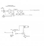
Tom. C1 is .32uF which is just a voltage set. Yes, its a choke loaded supply. I don't know what the 180uF didn't bring down the ripple at all. AC input voltage? 200 0 200
Too bad it will have no effect on the rectifier. Its a problem I guess with AC since the choke is coming off one of the filaments of the 5AR4 which is how its designed.
Tubes see 200V @ 12mA
Simon - I'll give it a try tonight. I measured everything else on the grounds...
Too bad it will have no effect on the rectifier. Its a problem I guess with AC since the choke is coming off one of the filaments of the 5AR4 which is how its designed.
Tubes see 200V @ 12mA
Simon - I'll give it a try tonight. I measured everything else on the grounds...
Let's try something...
Short circuit the choke and connect a 4.7 kOhm, 3 W resistor between the 40 uF and the 60 uF cap.
Now the supply is capacitor input. The 5AR4 should be loaded by 40+0.32 uF then follows an RC filter consisting of a 4.7 kOhm + 60 uF to GND.
In this configuration, I would expect about 250 V on the reservoir cap (40 uF). The current draw of the tube should result in a voltage drop across the 4.7 kOhm resistor of 56 V. The resulting B+ for the tube should then be 195 V. Close enough to the 200 that you want...
The resistor will dissipate 56^2/4700 = 667 mW so use a 2 W or 3 W type. In a pinch - just for the purpose of testing this - you could use four 18 kOhm 0.5 W resistors in parallel to form 4.5 kOhm.
The cut-off frequency of the 4.7 kOhm + 60 uF is 1/(2*pi*4700*0.00006) = 0.56 Hz. It's a single pole, -20 dB/dec (= -6 dB/oct) rolloff, so I'd expect -40 dB at 60 Hz. -46 dB at 120 Hz.
I would expect the ripple voltage on the reservoir cap to be:
V = i*t/C --> V = (0.012*(1/120))/0.00004 = 2.5 V, hence ,the ripple after the RC filter to be 46 dB less than 2.5 V = 2.5/200 = 12.5 mV.
That's my back of the envelope math anyway.
Choke input supplies are supposed to be rather hard to get to work well at low currents. I wonder if that's what you're up against.
~Tom
Last edited:
Thanks Tom. I'll give it a try. I've played with cap loaded and choke loaded and to my taste choke loaded sound better. But since this naked psu circuit was not breadboarded (sans its regulated supply) its a whole new world. I did find the one transformer needs better grounding as it had 3vac on the casing when I was playing around while the unit is playing trying to find any stray antennae event. I did a quick jumper grounding and it shunted the excess voltage to ground. It had no effect on the hum but I don't know if it affected the ripple. When I turn it off tonight I will ground it properly and measure.
While there may be some grounding perfections to carry out I just have the feeling this issue is simple if I could find where the AC is being injected into the circuit. Bud thinks its an 'antennae event ground loop'.
To let you know how low the hum is I shoved the phone into the speaker and he couldn't hear it. But now I tend to focus on it so it appears louder and louder.
- Status
- Not open for further replies.
- Home
- Amplifiers
- Tubes / Valves
- Anyone in the L.A. area with scope willing to troubleshoot?