Im learning how to use this o-scope and it is my first one.....
Im trying to see what the waveform of an unrectified 5V AC output looks like...
I have seen videos where folks use a 2 channel scope, without any of the ground clips on the probes for safety...
I gathered from you-tube vids, instruction manual (if you can really call it that) and just poking around the menus that
I should press the math button, than the add function and finally inverting channel 2...
No luck..
Without writing a novel, nothing I have tried will give me one waveform while testing the 5v ac out
What secret buttons do the job ?
Can you provide the link for this video?I have seen videos where folks use a 2 channel scope, without any of the ground clips on the probes for safety...
Why not just put the probe on one side of the 5VAC winding and the ground clip on the other?Im learning how to use this o-scope and it is my first one.....
Im trying to see what the waveform of an unrectified 5V AC output looks like...
I have seen videos where folks use a 2 channel scope, without any of the ground clips on the probes for safety...
I gathered from you-tube vids, instruction manual (if you can really call it that) and just poking around the menus that
I should press the math button, than the add function and finally inverting channel 2...
No luck..
Without writing a novel, nothing I have tried will give me one waveform while testing the 5v ac out
What secret buttons do the job ?
What you try to do is maybe necesasary if that 5V winding hangs off a 1kV source or so but I guess that's not the case.
Especially if that 5Vac is a secondary of a transformer, not connected to anything else, just probe it, no need for all kinds of complex stuff.
Try that when you got past Scoping 101.
Jan
Your oscilloscope is build to measure voltage, voltage can be measured only betwen 2 points, so you must use the ground clip and the probe ( use the ground clip attached to the side of the probe.
To have something easy to measure use a low voltage transformer 5 volts or 12 volts. Do NOT try to measure mains ! measuring mains need special precautions.
Basic notions:
input coupling 3 settings
1 ground no signal will be shown, only a reference line
2 direct coupling will show the signal and the reference line is the zero volts for the graph.
3 A C coupling will show the signal and the reference line is now the mean voltage of the waveform.
Vertical setting
Most of the time it is used as a voltage scale.
Horizontal setting
Most of the time it is used as a time scale.
Synchronisation
This is the most difficult part
A single sweep last only a few millisecond, the scope must redraw the graph many times a second.
The new graph must start at the same point of the waveform and start on the screen at the same point.
To do so you must
first choose synchronisation source if your signal is on chanel 1 set synchronisation source on chanel 1.
if your signal is on chanel 2 set synchronisation source on chanel 2.
then you select starting point on the waveform with ''synchronisation level'' and '' synchronisaton slope ''

I think the names on the scope are 'trigger' and 'triggering'.
Triggering ensures that the scope always starts a new display at the same time on the waveform which gives a visually stable display.
There's probably an 'auto' button in the trigger area, saves you some fiddling ;-)
BTW These things being discussed are not specific to any scope, they are general operating procedures although details may vary.
Jan
Last edited:
No matter how many times I played with the math function, I could not get the scope to perform.
There was one point where there were artifacts in the screen, I think Its a bad scope 😢
what the owners manual suggests the screen will look like, nevere happened ;-(
There was also very little room to get the ground lead alligator clip around solder terminal without bumping into another B+ lug,,,
That said, I do have high voltage differential probes... Kind of an ah ha moment...
Got the readings I needed, headed to another post re- 300B heater voltage !
If you are talking about ~46min of this video, he use isolated DIFFERENTIAL PROBE.
This is not the same as "2CH Scope"! It will also work with any 1CH scope.
There is no ground connection at the differential probe input, only 2 inputs.
With this probe you can measure the voltage between it's 2 inputs.
No matter what is the voltage between the measurement points and the ground (just it must be in the common mode and isolation range of the probe).
P.S. BTW, good differential probe costs more than this scope. Few times more...
You are 100% correct. I posted the wrong link.. trying to do too many things at once, my apologies...If you are talking about ~46min of this video, he use isolated DIFFERENTIAL PROBE.
This is not the same as "2CH Scope"! It will also work with any 1CH scope.
Im gonna start keeping notes of what I see and where as the time to find again takes 1000x longer than the actual content..
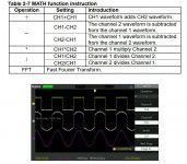
Below is a screen shot of the PDF for my scope, the middle wave is supposed to be a combination of the left and right channel....
In the video I saw, I thought the ground clips were removed.. Searching in earnest now to see If i can locate...
My accuracy in all things is not as consistent as I would prefer, that said may be not be 100% correct (plain wrong in other words lol)
Attachments
I have the same scope it works OK
May be triky ....
1 get the 2 chanels working with 2 signals
2 go to math fuction ... select '' + ''
3 then select the 2 signal to be added '' CH1 '' & '' CH2 ''
4 now I have 3 graphs yellow CH1 purple CH2 white MATH FUNCTION
5 go to second page of math function menu
6 now you have 2 buttons the upper one is for the position of the white graph the lower one is for the scale of the white graph both can be set using '' intensity control '' knob
should work !
Thank you, one question... does the ground clips need to be on both probes ?I have the same scope it works OK
May be triky ....
(I remember the entire purpose of this exercise was for when we don't want the low impedance to earth connection...)
This is more difficult to answer .. there is so many types of circuit .. type of tools .. type of probes .. and what do you expect to measure ..
there is no universal solution.
there is no universal solution.
ran across another video, this may be the one i was remembering.. Kind of feel like it was the one..
Hi,
the display picture in #10 shows a fully correct +Math trace.
Just keep in mind that Ch1 and Ch2 show different vertical scales.
Ch1 and Math both are set to 5V/div, while Ch2 is set to 2V/div.
Setting Ch2 to 5V/div would immediately show the correctness of the Math channel.
jauu
Calvin
the display picture in #10 shows a fully correct +Math trace.
Just keep in mind that Ch1 and Ch2 show different vertical scales.
Ch1 and Math both are set to 5V/div, while Ch2 is set to 2V/div.
Setting Ch2 to 5V/div would immediately show the correctness of the Math channel.
jauu
Calvin
In general - yes.does the ground clips need to be on both probes ?
Math mode CH1-CH2 can simulate the differential probe, but in many cases GND clips must be attached.
Why it works without this? Many scopes have connection between input's GND and PE contact. If the exploring device is also have the connection between it's GND to PE - both GND's will be connected together through the mains. Even without PE connection, due to a leakages and capacitances, it can "work".
But, it is not good for some reasons - this create a big loop, so you can get a lot of noise. Also scope's probe with it's cable will not operate properly at the high frequencies without GND clips connection.
So, if you want to measure the signal between 2 non grounded points - use or differential probe, or 2ch scope with math, but connect GND clips and pay attention to the voltage from these points to ground (not more than written at the probe and scope input).
- Home
- Design & Build
- Equipment & Tools
- Anyone here familiar with Siglent SDS 1102CML (1000 series) ?