Not bad sounding Amp if I must say!
This one has a scratchy vol pot, intermittent select switch...a good old raod map would be nice
Thanks in advance, Andjur78
This one has a scratchy vol pot, intermittent select switch...a good old raod map would be nice
Thanks in advance, Andjur78
Yes, I have the schematics of the Cambridge P40 but without the tone control. I can scan them. Just send an email to me.
~~~~~~ Forr
§§§
~~~~~~ Forr
§§§
andjur78 said:Not bad sounding Amp if I must say!
This one has a scratchy vol pot, intermittent select switch...a good old raod map would be nice
It's always good to have the schematics of one's amp.
But from what you say, diagnostic seems quite easy: clean or change the volume pot.
For the switch things may be more difficult. If it's not a rotary switch (I think the Cambridge had button-type selectors), then you will have to open the switch to clean it.
If it's rotary, go for a Grayhill switch which is a great deal.
Carlos
The volume control of the Cambridge is very special as it uses a virtual earth. Even before changing the 1 MOhm pot, change C1 and C2 (10 µF) which may be leaky.
~~~~~~~~ Forr
§§§
~~~~~~~~ Forr
§§§
forr said:The volume control of the Cambridge is very special as it uses a virtual earth. Even before changing the 1 MOhm pot, change C1 and C2 (10 µF) which may be leaky.
As far as I know there are no pots that use virtual earth per se. The designer is using virtual earth on the circuit, and the pot is connected to it. Any pot will do that.
But you are right that if there is a cap in the middle there shouldn't be any problem.
That cap may be a compromise that should be corrected before anything else. Different caps or no cap there should improve things a lot.
Carlos
Some volume controls use virtual earth with a pot, either used as a feedback resistor (Cambridge, from what I see from the schematics; I think it has a log variation) or both as input and feedback resistors in a circuit invented by Peter Baxandall and used by Douglas Self in his preamp. The great advantage of this last circuit relies in the use of linear pot, whose tracks, in stereo, match better than for the log type, the output being quite linear in dB.
~~~~~~ Forr
§§§
~~~~~~ Forr
§§§
I don't know if the P40 is similar, but my Cambridge had sliding selector switches operated by a sort of 'flat Bowden cable' arragement, which would be very difficult to source.
How good is the Sound Quality of the P40?
What would you compare it to?
I don't know much about this amp when was it made, it looks like it comes from the early 60's
What would you compare it to?
I don't know much about this amp when was it made, it looks like it comes from the early 60's
The first Cambridge amplifiers were one of the first :
- having a very tall fascia which, then used by Mark Levinson preamps.
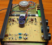
- using a toroidal transformer for the power supply, another manufactuer doing this was Tandberg.
~~~~~~~~ Forr
§§§
- having a very tall fascia which, then used by Mark Levinson preamps.
- using a toroidal transformer for the power supply, another manufactuer doing this was Tandberg.
~~~~~~~~ Forr
§§§
twelve years later...
... a thread hijack!
I've just obtained an 80's version of the P40, based on the same circuit I believe. Unfortunately the fuse ratings are not stated, either the power one or the two speaker protection ones. Someone has been inside this before, one speaker fuse fitted is 1A the other 5A! Does anyone know the correct ratings please?
Thank you in advance.
this is the one
An externally hosted image should be here but it was not working when we last tested it.
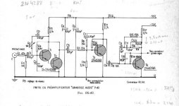
If it is indeed the same P40 circuit, a single 55V power supply rail will be in use and the audio output will be via a 2,500uF capacitor. This was augmented with an unusual form of current limiting in the original too - see sch. and comments on Paul Kemble's site: A Paul Kemble web page - the Cambridge Audio 'P' series amplifiers.
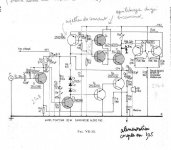
An output capacitor makes the need for fuse protection less critical but from the attached image ( courtesy of the same site as your pic of the later P40 model), I don't think it is the same design. Perhaps it shares some elements but this version appears to have a dual rail power supply, 2 pairs of output devices and no output cap. If it looks the same internally and the rail voltages measure more like +/- 25V, I would treat it as a different design and use 2A fast blow fuses in lieu of the 2.5 amp rail fuses said to be used in P50.
An output capacitor makes the need for fuse protection less critical but from the attached image ( courtesy of the same site as your pic of the later P40 model), I don't think it is the same design. Perhaps it shares some elements but this version appears to have a dual rail power supply, 2 pairs of output devices and no output cap. If it looks the same internally and the rail voltages measure more like +/- 25V, I would treat it as a different design and use 2A fast blow fuses in lieu of the 2.5 amp rail fuses said to be used in P50.
Attachments
Last edited:
- Status
- Not open for further replies.
- Home
- Amplifiers
- Solid State
- Anyone got schematics for the Cambridge Audio model P40?