anyone here built it?
if yes please share your experiences🙂
i need help with finding a compact transformer for the project that will fit a stomp box.
it also needs to have 220V primary.
there is a layout file in general guitar gadgets but it's in low quality🙁
if someone has a layout in good quality it will be of much help!
other than that any tips on the build for a toobnoob will be much appreciated.
How about a 1:1 220V 220V transformer from a "Shaver" socket? You'll still need to find 6/12 volts for the heaters, or alternatively two small 220V > 6V mains transformers back to back... you've got the heater volts then too from the middle 🙂
Here is a good build article on a yahoo blog
Original version
Translated version
Depending on how compact you wish the unit to be, several guys have used the 269EX Hammond on USA versions, and 369EX for multiple voltage needs.
Most certainly there are other options.
Original version
Translated version
Depending on how compact you wish the unit to be, several guys have used the 269EX Hammond on USA versions, and 369EX for multiple voltage needs.
Most certainly there are other options.
hey trout that link is very helpful! thx.
doz i rather buy a designated transformer...
else the sound engineer will always complain about my strat buzzing
i'll go for the hammond 369EX.
will this hammond enclosure fit the project (with the 369EX)?
http://www.hammondmfg.com/pdf/1456KH3.pdf
doz i rather buy a designated transformer...
else the sound engineer will always complain about my strat buzzing
i'll go for the hammond 369EX.
will this hammond enclosure fit the project (with the 369EX)?
http://www.hammondmfg.com/pdf/1456KH3.pdf
One option would be to have the PSU a bit farther away in a separate box, thus alleviating the space dilemma.
How about a 1:1 220V 220V transformer from a "Shaver" socket? You'll still need to find 6/12 volts for the heaters, or alternatively two small 220V > 6V mains transformers back to back... you've got the heater volts then too from the middle 🙂
You could use an external 12VAC plugpack for the stepdown. A 220V to 12V transformer could then be used "backwards" inside the main box as a stepup for the B+ supply. The 12VAC would also power the 12AX7 heaters.
You could use an external 12VAC plugpack for the stepdown. A 220V to 12V transformer could then be used "backwards" inside the main box as a stepup for the B+ supply. The 12VAC would also power the 12AX7 heaters.
sorry for this question i'm a bit of a noob in this😱
won't this combination make more hum or noise than a designated transformer?
hey trout that link is very helpful! thx.
doz i rather buy a designated transformer...
else the sound engineer will always complain about my strat buzzing
i'll go for the hammond 369EX.
will this hammond enclosure fit the project (with the 369EX)?
http://www.hammondmfg.com/pdf/1456KH3.pdf
There is no reason 2 transformers will create any more hum than one, in fact you will end up with more noise filtering.
There is no reason 2 transformers will create any more hum than one, in fact you will end up with more noise filtering.
Very true,
In fact, it is common to use 2 transformers for tube driven pedals. That way you can plug the wall wart needed into a standard pedal board strip.
Bonus, it cuts down on chassis space as well.
In all honesty I was surprised to see that pedal set up with a conventional PT.
The Hughes Kettner Tubeman uses a small internal transformer (12V to 250V) and a walwart 120V - 12V.
They run the 12AX7 filament on 12V rectified rather than 6.3V.
It just depends on how accurate you want to clone the pedal.
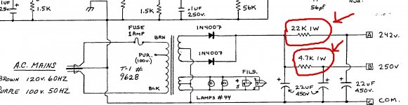
according to the schematic the B+ for V1 is supposed to be 242V
so if I use a 220V to 12V backwards won't i get only 220V?
An externally hosted image should be here but it was not working when we last tested it.
so if I use a 220V to 12V backwards won't i get only 220V?
Err, Yes--
220V....
But THATS AC!
So, after rectification, smothing and assuming silicon recs and no losses that'll give you--311V DC....
--So, with careful PSU design you can lose many volts and have exactly the volts that thing needs.....
220V....
But THATS AC!
So, after rectification, smothing and assuming silicon recs and no losses that'll give you--311V DC....
--So, with careful PSU design you can lose many volts and have exactly the volts that thing needs.....
I have an incomplete project in eagle I can share with you, would save you some time I think. send email address by pm, I don't think we can attach eagle files.
here it is in zip format, it is about 95% complete, would need to check sch file against prited circuit schematic to check for any errors. It is quite old and was never intended to be a public project so it lacks some finesse.
PS, make all the route layers at the top visible to see how to wire up the pots.
Like allready pointed out, your mains voltage rectified would be about 373VDC. You might have to go up or down a size with the PSU resistors to get it perfect, but these things are forgiving.
PS, make all the route layers at the top visible to see how to wire up the pots.
Like allready pointed out, your mains voltage rectified would be about 373VDC. You might have to go up or down a size with the PSU resistors to get it perfect, but these things are forgiving.
Attachments
Last edited:
ah yes forgot about that😱Err, Yes--
220V....
But THATS AC!
ok i did some home work.
using 2*1N4007 rectifying 220V will give me approx 311Vdc(220*1.414)
as stated earlier by Alastair E.
the first reservoir capacitor needs to be approx 47uf (please correct me if i'm wrong i am learning this stuff as we speak)
C=(0.083*0.02)/31=4.76
as for the voltage dropping resistor this is where i get confused...
in the schematic i posted before , there are 2 dropping resistor for each tube
(are the marked resistors are the dropping resistors??)
when i calculated the resulting voltage after the drop i didn't get the voltage drawn in the schematic:
original project using Hammond 269EX:
380Vac*1.414=537Vdc
537Vdc-250=287
so 287/0.02=14Kohm according to my "skilled" calculations this should be the value.
it is 4.7Kohm in the schematic

going to the reversed 220V suggested here is the dropping resistor should be:
311Vdc-250=68V
68/0.02=3.4Kohm
is this calculation right?
i looked at the tube newbie sticky couldn't find an answer!honest!
where did i go wrong??😕
Attachments
The closest you will get to the original Hammond transformer (which I don't reccomend you getting as they were the weakpoint of the hotbox, and failed easily), Search for P-T269JX at Antique Electronic Supply it does 250-0-250 @60mA and has a 6.3V 2.5A winding for heaters., they used to have a 50mA version which was only $20, maybe you can enquire...
ohhh now i see my mistake...
it's 190Vac*1.414=268Vdc
and these resistors are just part of the RC filter...
no dropping resistor there.
digits i need 220V primary so that p-t269JX won't do.
i think i'll go with the 369EX and stick to the schematic.
i don't have enough knowledge to start experimenting.
thanks for all your help
will update when i start building.
ohhh now i see my mistake...
it's 190Vac*1.414=268Vdc
and these resistors are just part of the RC filter...
no dropping resistor there.
digits i need 220V primary so that p-t269JX won't do.
i think i'll go with the 369EX and stick to the schematic.
i don't have enough knowledge to start experimenting.
thanks for all your help
will update when i start building.
This is how The Hughes Kettner tubeman used 2 transformers.

the first reservoir capacitor needs to be approx 47uf (please correct me if i'm wrong i am learning this stuff as we speak)
C=(0.083*0.02)/31=4.76
Hello,
I'm new in this business and I don't understand these calculations, would you mind to explain it?
Have you tried it with two back to back tranasformers?
Thank you.
Miquel
wow this thread is dusty.
my hot box project ended up as JCM800 preamp in a box🙄
seeing my questions in this thread now... what a toob noob
here is a video i made :
DIY marshall JCM800 preamp in a box - YouTube
my hot box project ended up as JCM800 preamp in a box🙄
seeing my questions in this thread now... what a toob noob
here is a video i made :
DIY marshall JCM800 preamp in a box - YouTube
 Going to move this to the Instruments & Amps forum that did not exist at the time this thread was originally created.. 😀
Edit: Done
- Status
- Not open for further replies.
- Home
- Live Sound
- Instruments and Amps
- anyone built the matchless hotbox?