Just interested to know, because I have started mucking around with switchmode powersupplies again, and have FINIALLY managed to get it to actually do something.... that is, with 9 volts in, I saw 26 volts out.. 🙂 I intend on using 2 transformers, one for each rail, and the feedback pin on the ICto get somewhere between 25 and 30 volts.. 🙂 (+-)
anyway.. anyone had any sucess? 🙂 THANX!
anyway.. anyone had any sucess? 🙂 THANX!
I got the low power version one going from www.sound.au.com (Rod Elliot site). I produced about +15 and -15 from 12V input. However, the voltage sag was terrible, I think because my output inductors were too small. I plan on making a serious attempt at a higher power version. I think it can be done, and I don't think its that hard, but I do think that you really need to know what you're doing. Therefore I'm going to get a good book and read it (like I did with Sloan's amp book, which has become my bible so to speak).
It's a shame that my electrical engineering degree (of which I've got one more semester to go) doesn't contain any electronics. I found it funny that we cover basic op amp (inverting, non-inverting, followers, etc) theory in my fourth year electronics 3 course. If it wasn't for resources like this forum I'd be like my peers and have a 4th year electrical engineering degree, and know nothing about electronics.
Pete
what are all these problems people always talk of? what is so hard about it??
I now have an adjustable +- voltage (adjustable from 20 to 30 volts) from the single transformer, its really too small to run an amp though, but I'll still give it a try.. 🙂
I now have an adjustable +- voltage (adjustable from 20 to 30 volts) from the single transformer, its really too small to run an amp though, but I'll still give it a try.. 🙂
well.. the amplifier runs.... BUT!!! the rectifier diodes get TOO HOT!! 
I am using the rectifier diodes from a couple of old computer powersupplies, they are the ones from the 5 volt rail... maybe they aren't rated at 30 volts... hmm.. anyway, they are on the same size heatsink as they were on in the computer powersupply, and should only be passing like 2 amps.... probably less actually, but the heatsink gets hot enough to BURN me.. any ideas? lol apart from that, the amp works... it was cutting out, then not coming back on for a while, but I think that may have been because the diodes were cooking.. 😛
EDIT: I am NOT using low ESR capacitors at the moment, would this be the problem? thankyou... 🙂
I am using the rectifier diodes from a couple of old computer powersupplies, they are the ones from the 5 volt rail... maybe they aren't rated at 30 volts... hmm.. anyway, they are on the same size heatsink as they were on in the computer powersupply, and should only be passing like 2 amps.... probably less actually, but the heatsink gets hot enough to BURN me..
any ideas? lol apart from that, the amp works... it was cutting out, then not coming back on for a while, but I think that may have been because the diodes were cooking.. 😛 EDIT: I am NOT using low ESR capacitors at the moment, would this be the problem? thankyou... 🙂
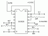
A built a Elliot SMPS (SG3525 based) and it worked perfectly. I had an initial problem of to little primary turns but after that was sorted I got +-35v very stable.
I ran two p3a's off it and it sounded great (except on my friends car that had the regulator removed...). It only got cranked to about 25w rms each amp coz his speakers where quite poor and my bedroom ones are only 30w rms.
 )
)
They make smaller ones also if your feeling light hearted. If you can't get low ESR caps just paralell lots of 1000uf caps and you get the same results (or lower if you only using like 2200 uf worth)
I think I'm to eager to use dual 8.5cm ferrites
I ran two p3a's off it and it sounded great (except on my friends car that had the regulator removed...). It only got cranked to about 25w rms each amp coz his speakers where quite poor and my bedroom ones are only 30w rms.
Onsemi make 200a ultra fast diodes for sample 🙂 I've got enough to make my next beasty amp (hoorah for kilwattsany ideas?
)They make smaller ones also if your feeling light hearted. If you can't get low ESR caps just paralell lots of 1000uf caps and you get the same results (or lower if you only using like 2200 uf worth)
I think I'm to eager to use dual 8.5cm ferrites
Yeah i'm still designing mine, like i've got a schematic done fairly close to robs, and then trying to make a neat single sided pcb (not really possible). I've had some helpful hints from this forum, like the output inductor thing i haven't decided on yet, but i might try them if the voltage feedback fails to work.
SkinnyBoy said:what are all these problems people always talk of? what is so hard about it??
SkinnyBoy said:well.. the amplifier runs.... BUT!!! the rectifier diodes get TOO HOT!!
Maybe you have given yourself a couple of answers....SkinnyBoy said:

Good, effecient, non-emitting SMPS is nothing for amatuers. It IS hard to build from scratch without knowledge or instruments.
It's not hard to build if you have a ready made pcb with good instructions but where are they...
actually.. it works now... for some reason, the diodes didn't like being mounted on the same heatsink, with one insulated from the heatsink, and the other not insulated....
I can now adjust the rails from +- 12 volts to +- 30 volts.. 😀 the higher the voltage, the cooler the mosfets run, I think I will use +-20 volts for now, as I am not too sure about the transformers I am using...
anyway.... I have no knowledge, I have an oscilliscope, and I don't have a ready made PCB.... what problems should I be encountering?
well with those supply rails and good current...you could use a "normal" amp circuit inside...except that you use an SMPSU to power it up...be careful with RF and stuff...
li_gangyi said:well with those supply rails and good current...you could use a "normal" amp circuit inside...except that you use an SMPSU to power it up...be careful with RF and stuff...
ahh.... whats a not normal amp???? 🙄
I have used it with an LM3886 based amp.... it runs it quite well, but you can tell its a switchmode powersupply by the sound....
i'm planning to do elliots smps, with +-25V rails to run two 3886's @ 50Wrms
actually i was going to startt doing it today, but i slept too long and couldn't get SG3525 and IRF540's
and a question, how big should toroid be for +-25V@10A? I have some toroids from old computer psu's, but i think they are too small.
actually i was going to startt doing it today, but i slept too long and couldn't get SG3525 and IRF540's
and a question, how big should toroid be for +-25V@10A? I have some toroids from old computer psu's, but i think they are too small.
goodluck... lol
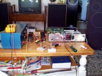
first picture is "everything"..... blue powersupply was in the end set to 18 volts as it has a 2.5 amp limiting circuit, and the voltage was dropping a fair bit, even with it set to 18 volts no load, it still dropped to less than 9 volts when the volume was turned up...
the amp I ran from it was the one I am/was building into a CD player case with a computer... I think I'll scrap the idea... 😛
Attachments
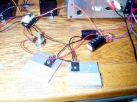
here we have the diode thingos mounted on their own heatsinks, not insulated from them... when you touch the heatsinks, the amplifier goes off... lol
the transformer, some filter capacitors, and outout inductors.. 🙂 and the pot I have been using to adjust the voltage.. 🙂🙂
the transformer, some filter capacitors, and outout inductors.. 🙂 and the pot I have been using to adjust the voltage.. 🙂🙂
Attachments
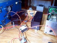
li_gangyi said:pretty cool...but if you keep the mosfet's leads short...the efficiency could be improved...
you really are full of ideas, aren't you....
lolthe leads will be as short as is practicle, and possible..... you may have noticed that it doesn't all fit in the case yet... lol
hmm.. the whole time I was sleeping no one replied, even though like 30 people looked at this thread, or one person looked at it 30 times... lol
EDIT: My mum really had to put up with alot... lol
thanx mum 🙂
EDIT: My mum really had to put up with alot... lol
thanx mum 🙂
- Status
- Not open for further replies.
- Home
- General Interest
- Car Audio
- Anyone actually suceeded in making a car amplifier?