F = Farads, a measure of the capacitance. (not f = femto)
m = milli, the multiplier in this case 10^-3 but commonly misused instead of u (10^-6)
eg 470pF or 220uF
Sakis,
you should know better than confuse folk.
m = milli, the multiplier in this case 10^-3 but commonly misused instead of u (10^-6)
eg 470pF or 220uF
Sakis,
you should know better than confuse folk.
sorry Andrew but as you all know English is not my native language and given this as a fact i thing i manage quite well
also anyone that seen amplifier before can understand the value from the location of the part ....
Lets focus on the circuit
also anyone that seen amplifier before can understand the value from the location of the part ....
Lets focus on the circuit
it has Andrew ..... mikro is a Greek word and in our country we write and mean microfarad ....so spelling is mfd
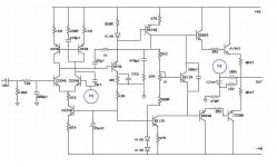
The VBE multiplier 680R base resistor is connected at a wrong place.
The differential current is barely 60uA...
Other than that , this amp seems to be a complete disaster....
The differential current is barely 60uA...
Other than that , this amp seems to be a complete disaster....
Looks like a couple of typos...
1) The 680R resistor in the Vbe multiplier should be connected to the collector of the BD139 below it, not it's base.
2) The 22K resistor in the CCS feeding the LTP looks wrong. Is it supposed to be 2K2?
3) The 10K resistor in parallel with the 330pF cap, connected to the collector of the first VAS transistor, should perhaps be 1K?
1) yes you are correct this is just a drawing mistake
2) verified with the designer the resistor is 22K
3) verified with the designer the resistor is 10K
2) verified with the designer the resistor is 22K
3) verified with the designer the resistor is 10K
I've drawn a blank with SPICE models for the BD829 and BD830. Can I substitute them with something else like the MJE243 and MJE253? The fT is a lot lower though.
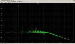
High frequency THD is awfull , wich is a consequence of the "design choices" ,
mainly the low differential current.
As spoted by Godfrey the CCS resistor should be reduced to 2.2K while
the 33K must be also reduced to 3.3K or suppressed.
In the meantime the current mirror emitter resistor should be reduced
to 220R.
Of course the amp become way faster with theses mods , so the
compensation has to be adapted , best is to suppress the shunt network
consisting of 27R + 470pf , replace the 22pF cap by a 100pF and replace
the serial 1K resistor by a short.
Also , a zobel output network should be added.
Below is the simulated THD at 10KHZ 25W RMS 8R.
Attachments
Last edited:
The 829/830 are in fact the 100V version of the BD139/140.I've drawn a blank with SPICE models for the BD829 and BD830. Can I substitute them with something else like the MJE243 and MJE253? The fT is a lot lower though.
I found the missing models for the BD829/BD830. Here they are...
.MODEL BD829 NPN (IS=9.530E-0019 NF=714M NR=714M RE=170M RC=1 RB=10 VAF=40 VAR=20 ISE=236F ISC=236F ISS=0 NE=1.5 NC=1.5 NS=1 BF=74.9 BR=5 IKF=878M IKR=878M CJC=131P CJE=131P CJS=0 VJC=515M VJE=515M VJS=750M MJC=330M MJE=330M MJS=0 TF=637P TR=82.8N EG=1.11 KF=0 AF=1)
.MODEL BD830 PNP (IS=1.130E-0018 NF=714M NR=714M RE=159M RC=1 RB=10 VAF=40 VAR=20 ISE=2.79F ISC=2.79F ISS=0 NE=1.24 NC=1.24 NS=1 BF=106 BR=5 IKF=525M IKR=525M CJC=131P CJE=131P CJS=0 VJC=515M VJE=515M VJS=750M MJC=330M MJE=330M MJS=0 TF=2.12N TR=276N EG=1.11 KF=0 AF=1)
Google/Yahoo was of no help. Don't ask me where I got them, hehehe.

now ...wahab obviously we are missing something here .
Ingenious ...thanks very much for your time and effort did you see something else that troubles you ?
kind regards sakis
Ingenious ...thanks very much for your time and effort did you see something else that troubles you ?
kind regards sakis
now ...wahab obviously we are missing something here .
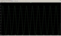
10kHz vs. 1kHz THD?
I am afraid that the slew rate is rather abysmal. Even at 6kHz, the waveform is already badly distorted. At higher frequencies the output is a triangle wave, for a sine wave input.
I left out the 330pF cap by accident, but the results remain the same if I put it in.
I left out the 330pF cap by accident, but the results remain the same if I put it in.
Attachments
Last edited:
- Status
- Not open for further replies.
- Home
- Amplifiers
- Solid State
- Anybody willing to simulate ?