We have good experiences with both FKPs and PPS caps.
We use PPS where we want a compact layout and small values (like 150p).
We find silver mica a touch bright for analog filters.
Where space is not a restriction, we want best properties and larger values, we use FKP, or MKP.
Best is still styroflex.
Patrick
We use PPS where we want a compact layout and small values (like 150p).
We find silver mica a touch bright for analog filters.
Where space is not a restriction, we want best properties and larger values, we use FKP, or MKP.
Best is still styroflex.
Patrick
Last edited:
yep, if it werent for the odd pckage I would use the relcap styrenes in place of the FKP, but the diagonal lead placement makes them a pita to work with.
qusp, how to measure and design the source and receiver resistors? My old 10 MHz Hameg might help for LRCLK but for MCLK (e.g. 49.152 MHz) even a 100 MHz scope only shows 1st and 2nd harmonic? I guess not many will be able to test and design suitable values for their specific application 😕
And what about the effect of having 0R resistors compared to just a trace?
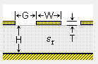
If I want to have 50 Ohm impedance for the clock lines, TXline gives me 0.75mm trace width (1mm FR4, 35µm, 0.15mm gap) if I have a solid ground plane on bottom layer and surround the lines with GND on top layer. Would you agree?
Just as a small upgrade another version 🙂
well we kind of need more information than the above and its difficult, because the exact thickness and dielectric constant of the FR4 vary from batch to batch and the dielectric constant also varies depending on frequency. You need to use Duroid or some other higher quality Rogers PTFE or ceramic substrate to get something more stable and allow more arbitrary rules of thumb.
.75 doesnt seem thick enough to me. for example with a trace thickness of 35µm, with 150µm gap and 1mm board which leaves us 815µm substrate. if we just give an estimation of Er = 4, I get 1.6mm trace width for 49Ω (1.555mm for exactly 50Ω)
here is a good calculator (use microstrip for this calc), which PCB layout package are you using? Eagle? does it have the ability to handle these calculations for you?
the zero ohm resistor.. hmm yeah I nearly mentioned those, I would think they are problematic, but I cant suggest an alternative, this is where flip-flops/clock buffers with 2 inputs might be handy?
Last edited:
I assumed a grounded coplanar waveguide (see attached diagram). It is not available in the online calculator in your link but i found a tool here. Does not yet correspond to my board, however thought about adding a second groundplane on toplayer (with lots of vias). By the way: I am using Target! as design tool (just got used to it).
Having said that, I am not really sure if it makes sense to go too deep into those things. As you said, to make it really good you have to control many parameters which will be quite hard in a hobby project like this. I'll try to make some good estimations to come close to 50Ohm and that should be enough 😉
I'll try to order pcb's this week. Any special recommendation? makePCB was very cheap, but communication and quality were not really top-notch...
Attachments
Hi! I just became aware of this thread...
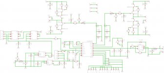
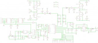
Very nice work! I Really like the clean schematics and your strive for a good PCB layout on a two layer board. If you intend to order multiple PCBs (even for beta testing) please count me in for one.
Thanks!
Very nice work! I Really like the clean schematics and your strive for a good PCB layout on a two layer board. If you intend to order multiple PCBs (even for beta testing) please count me in for one.
Thanks!
Hello all. I did some more rework. Please find attached the latest version.
When I order boards, some will be left for a few beta tester if there is interest 😉
Best regards, Daniel
When I order boards, some will be left for a few beta tester if there is interest 😉
Best regards, Daniel
Attachments
Hello all, please find attached the latest version, which I will order this weekend. Those who asked for prototypes are on my list and will be contacted by PM.
Best regards, Daniel
Best regards, Daniel
Attachments
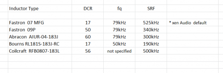
There has been discussions about the type of inductors used in the Joachim Gerhard Filter.
I thought it would be more appropriate to continue the discussion in the original technical thread.
So I summarised it here (see attached).
As Joachim mentioned here :
http://www.diyaudio.com/forums/grou...hard-filter-buffer-es9022-10.html#post3373106
"....... High self resonance of the coil helps to make the filter work ( drop aliasing products ) up to very high high frequencies where is not much energy any more. A low self resonance of the coil will change the slope of the filter. The coil looses inductance there, first there is a minumum ( actually an inductance maximum ) and then the coil gets capacitive so there is a rise in frequency. It simply does not work like a theoretically perfect coil any more over the resonance frequency.
First i had objections to use a ferrite coil but i testet the sound of the Faston compared to a very expensive Sowter coil and got a very satifying result. It sure does not sound hard or distorted. Quite the contrary, smooth and liquid and that was what i wanted.
I found the "untreated" ESS DAC a bit on the brittle side and that effect disapeared with my filter-buffer."
Patrick
Attachments
For your Info: just ordered some boards for beta testing. I will put together a BOM soon, though I don't plan to specifiy concrete parts (e.g. brand), just suggested value and size of parts.
May take another two or three days since I have to care for my family (in Germany influeza is everywhere these days 🙁)
Best regards, Daniel
May take another two or three days since I have to care for my family (in Germany influeza is everywhere these days 🙁)
Best regards, Daniel
dear Daniel,
thanks for putting so much effort and energy in this project and also updating us (potential betatesters/customers) with the BOM and all the possible construction advices all the way;
do you already have a hint for the prices of these boards? if you can't write it here, please pm
I also think that your project would be a great succes in case of a group-buy because it has all the stuff one can posibly build around the ES9023 and beside this you move very fast and have everything ready
That's how I understand this forum 😉 It is great fun to share a project and to discuss possible optimizations.
Currently I don't plan a group buy on my own since my personal situation doesn't give me the time needed. However I am generally open to privide the design for a groupbuy after successful betatest (I have the approval from Joachim to use his filter buffer design!). Those who already contacted me with respect to betatest will get a PM soon. All the others please be patient. If the board works well I will see how many boards I have left.
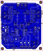
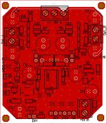
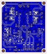
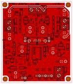
@samoloko: not sure I understand your question. The board I ordered indeed has a green soldermask though this is some kind of taste 😉 The above shown layouts (blue and red) just show top and bottom layer of the PCB, not soldermask!?
Currently I don't plan a group buy on my own since my personal situation doesn't give me the time needed. However I am generally open to privide the design for a groupbuy after successful betatest (I have the approval from Joachim to use his filter buffer design!). Those who already contacted me with respect to betatest will get a PM soon. All the others please be patient. If the board works well I will see how many boards I have left.
@samoloko: not sure I understand your question. The board I ordered indeed has a green soldermask though this is some kind of taste 😉 The above shown layouts (blue and red) just show top and bottom layer of the PCB, not soldermask!?
Thank you for your effort Daniel.
Do you already have the ES9023? As far as I understood they could be bought only from Ismosys here in Europe but I don't know if they sell in small quantities.
Do you already have the ES9023? As far as I understood they could be bought only from Ismosys here in Europe but I don't know if they sell in small quantities.
> As far as I understood they could be bought only from Ismosys here in Europe
Correct.
> but I don't know if they sell in small quantities.
They charged (me at least) 75€ to a UK address, and 100€ to address in the EU.
You can then order any quantity you want.
Whether the have changed their policy now, you better contact them directly to find out.
Patrick
Correct.
> but I don't know if they sell in small quantities.
They charged (me at least) 75€ to a UK address, and 100€ to address in the EU.
You can then order any quantity you want.
Whether the have changed their policy now, you better contact them directly to find out.
Patrick
I only have a few ES9023 that I will need myself, sorry.
Not sure if this is still valid but I had no problem to order small quantities at Ismosis. You should get in contact with your local representative before you order, since the standart shipping charge is 75 Euro. For small quantities (wrapped envelope with registered airmail) they reduced it to 20€.
As an alternative try ebay. There was a link here in the forum (one of the ES9023 related threat AFAIK) to a seller that was said to be reliable.
Daniel
- Status
- Not open for further replies.
- Home
- Source & Line
- Digital Line Level
- Anybody using the new ESS Vout DAC (ES9022)?