Douglas, I too just downloaded XSim. How do I 'jump' wires over wires?.
When you get the little spool cursor, click, drag the wire to your target and let go. Lines that cross are not joined. Lines with dots at their intersections are joined.
The quasi second order was introduced in a paper presented by J. Robert Ashley and Allan j. Kaminsky . "Active and passive Filters as Loudspeaker Crossover Networks". JAES June 1971.The component values are calculated as follows:- C=zeta/R.2.Pi.f and L=R/zeta.2.Pi.fHello
I use Xsim for the first time, and I'm trying to do quasi 12 db (quasi second order) series 3 ways crossover, crossover frequencies at 150 hz and 2500 hz, but I have few difficulty to succeed. I include the Xsim simulation file, anybody can help me ?
Thank
Bye
Gaetan
zeta can be 1 as in the case of a first order Butterworth filter. The authors proposed zeta = 0.707 and 0.5. There never appeared to be much interest in this type of series filter and that me have been due to the published curves and charts not being accurate. Erik Baekgaard in a late paper suggested a value for zeta =0.8165. JAES May 1977.
Basically all zeta values less than one will result in a dip in the response at the crossover frequency, more noticeably at a value of 0.5.
Stepping the drivers on the baffle to correct the for phase errors is beneficial as is impedance correction for bass/ midrange speakers.
The values shown in previous replies for the drawn network are in the wrong places and there is no need to correct an inductor value by subtracting the smaller one from the 150 Hz calculation.
Last edited:
I use Xsim for the first time, and I'm trying to do quasi 12 db (quasi second order) series 3 ways crossover, crossover frequencies at 150 hz and 2500 hz, but I have few difficulty to succeed. I include the Xsim simulation file, anybody can help me ?
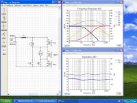
I've included a second version below that is tuned to the more 1970s range of 500 and 3000 hz. Compare it to the original and note the value changes...
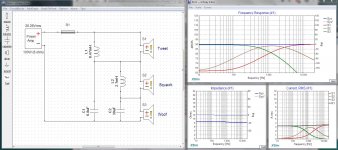
Open the DXO file then, using the menus on each panel, open the curves as shown.
Pick a component... any coil, cap or resistor, right click on it, select tune and you can play with it's value. You can use the spinner control or the up and down arrow keys. Go one or two clicks up or down and see what changes ... now you know what parts do what. Then you can simply manoeuvre the parts values as you need to.
I added R1 into the schematic to simulate speaker wire (which is why it's shorted). It also allows me to open auxiliary panels such as current and power to look at what parts are operating efficiently and which are not.
It takes a while to get the hang of it but XSim is very useful.
Attachments
Maybe it would help to simulate the three-way series crossover using the second drawing shown in the Tube Cad discussion
More on the Series Crossover
More on the Series Crossover
As a learning exercise it's probably a good idea to try them all.
Hello
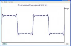
How can we see the resulting square wave response of all the drivers combined
with XSim ?
Thank
Bye
Gaetan
How can we see the resulting square wave response of all the drivers combined
with XSim ?
Thank
Bye
Gaetan
Last edited:
How can we see the resulting square wave response of all the drivers combined
with XSim ?
Look in the menu bar at the top of the main window... click on Add Graph... then More and you will find all kinds of extra panels to look at.
Look in the menu bar at the top of the main window... click on Add Graph... then More and you will find all kinds of extra panels to look at.
Hello
OK
Thank
Bye
Gaetan
Hello
Gaetan
Am I the only one who doesn't understand how this crossover works?😕
Am I the only one who doesn't understand how this crossover works?😕
Yup
Understanding series crossovers is both easy and hard.
Start at the amplifiers binding post. In your mind, only visualize the positive (rising) portion of the sinusoidal waveform (music). This voltage pushes the driver out. Pick a frequency, say 10,000 Hz. The first inductor blocks this frequency, so that path is cut off. The positive portion reaches the tweeter. It moves.
The frequency, however, is part of a flow (think current). Because the tweeter has a capacitor on the negative portion, and caps only allow high frequencies, only high frequencies pass 'through' the tweeter.
Now go to the other end of the spectrum, 100 Hz. It easily passes through the inductor.
Its best to print out the crossover, get a few different colored markers, and trace the path of different frequencies.
Well done. Where will you go from here. Will you build it and then add resistors to your tweeter and mid?I have succeed to do a crossover using Xsim.
Well done. Where will you go from here. Will you build it and then add resistors to your tweeter and mid?
Hello
Yes
Gaetan
Hello
I have succeed to do a crossover using Xsim.
Here it is.
A very good first exercise in learning how to use Xsim to simulate a series circuit. Well done. 🙂
Note that isn't a crossover per se except electrically, assuming pure resistors as the load, just as the Tubecad writeup was. Your next step will be to take the measured on-baffle frequency and impedance responses for each driver you are using, and enter those into Xsim to work with.
- Home
- Loudspeakers
- Multi-Way
- Anybody can give me thoses formula for that crossover ?