Hello
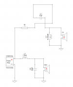
I found an interesting 3 way series crossover circuit, but there is no formula to calculate the values of the parts.
Anybody can give me thoses formula for that crossover for 8 ohm drivers ?
I need the crossover frequencies at 150 hz and 2500 hz
Thank
Bye
Gaetan
I found an interesting 3 way series crossover circuit, but there is no formula to calculate the values of the parts.
Anybody can give me thoses formula for that crossover for 8 ohm drivers ?
I need the crossover frequencies at 150 hz and 2500 hz
Thank
Bye
Gaetan
Attachments
Last edited:
Depends on which drivers you use, the size of the box, etc. That's just a generic circuit and is unlikely to do very well as is.
Hello Geatan.
Start by going to ml-audio HiFi Loudspeaker Design
Find your way to calculator / crossovers / Series Linkwitz - Riley '2-way'.
It is the 2-way 2nd order that you want. It may not make sense, but trust me. HiFi Loudspeaker Design
The first driver / component you find is L2. This is the crossover point to the tweeter. You need to know the impedance of the midrange at the frequency you want to cross. Since inductor values are less varied than capacitors, this is the easiest place to start. You vary the frequency in the calculator until you get the exact inductor value which is easily obtainable. This gives you your new theoretical crossover point.
With this new crossover point, you start over, this time for the tweeter. What is the impedance of the tweeter at that new crossover frequency. Input in the calculator. Now you have C2.
Repeat for L1 and C1.
Which amplifier are you using? What is its output impedance?
L1 8.49 minus 0.51 mH, C1 132uF
Hello
So it would be the values of the parts in this image ?
Thank
Bye
Gaetan
Attachments
I doubt it. That image is taken from the bollocks on Tubecad. The topologies are all very interesting, but unfortunately what simulations were done on said blog were generated in SPICE, and assume all drive units to be pure resistors with coincident acoustic centres. In other words, they assume that all the loudspeaker drive units exist at the same physical point in space, and furthermore assume that the frequency and impedance response of the drive units are ruler flat from 0Hz to infinity.
Which is bollocks.
If you don't want to be randomly swapping components in your filter until the four horsemen start riding (series filters being a total swine for empirical testing due to everything being in circuit all the time), you'll be better off simulating it. For that you need the frequency and impedance responses of the drive units taken on the baffle you are using them on, and enter it into an appropriate modelling program. In this case you'd need a free-form modeller, so LspCAD, Soundeasy, Xsim, Boxsim or VituixCAD are the popular options.
Last edited:
Scott is correct. This crossover is a bit of a nightmare.
I've built three speakers with this crossover, and have started on my fourth. When done judiciously, the sound is amazing, but it's still a nightmare.
There is NO way of buying random drivers and hooking them up.
L-pads, LCR's etc., only turn this into a mess. I can't remember the gentleman's name, but he tried and gave up. Parts count approached 45 caps and inductors. Yikes!!!
Basic starting point; the woofer will be 3dB more efficient than the mid and tweeter (baffle loss). If the midrange baffle width, and therefore the baffle step is chosen carefully (read really wide, like the old style speakers, no baffle loss), than it can be the same sensitivity as the tweeter. Finding those drivers, and building a really wide speaker, not easy or pretty.
Because of all the problems, I actually find it easier to build a 4-way series than a 3-way.
Last edited:
I doubt it. That image is taken from the bollocks on Tubecad. The topologies are all very interesting, but unfortunately what simulations were done on said blog were generated in SPICE, and assume all drive units to be pure resistors with coincident acoustic centres. In other words, they assume that all the loudspeaker drive units exist at the same physical point in space, and furthermore assume that the frequency and impedance response of the drive units are ruler flat from 0Hz to infinity.
Which is bollocks.
If you don't want to be randomly swapping components in your filter until the four horsemen start riding (series filters being a total swine for empirical testing due to everything being in circuit all the time), you'll be better off simulating it. For that you need the frequency and impedance responses of the drive units taken on the baffle you are using them on, and enter it into an appropriate modelling program. In this case you'd need a free-form modeller, so LspCAD, Soundeasy, Xsim, Boxsim or VituixCAD are the popular options.
+1
If you are lucky, the Tubecad values may provide a crude starting point for "real" drivers, but no guarantees. Good driver measurements and simulation software (along with some luck and a lot of patience) might get you a viable solution.
While Scott is not incorrect, crossovers generally face these issues and challenges.
The acoustic coincidence issue is just a matter of filter damping. The issue of unrealistic impedances is actually used to advantage in many modest designs. It's one of the benefits of the series crossover, and most crossovers are not that straightforward.
The acoustic coincidence issue is just a matter of filter damping. The issue of unrealistic impedances is actually used to advantage in many modest designs. It's one of the benefits of the series crossover, and most crossovers are not that straightforward.
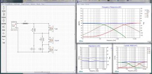
Just for giggles ....
Using @Adason's values.
Using @Adason's values.
Attachments
Last edited:
Just for giggles ....
Using @Adason's values.
Hello
I just found XSIM in the forum, seem very good.
Here's the link to XSIM
XSim free crossover designer
Thank
Bye
Gaetan
Last edited:
Hello
So it would be the values of the parts in this image ?
Thank
Bye
Gaetan
yup
you will likely encounter drivers with different efficiency, you may need L-pads on mid and tweeter
otherwise don't get discouraged by negative posts, nothing is stopping you to experiment
it would help to have umic and do some real measurements with real speakers
software is free
good luck
otherwise don't get discouraged by negative posts, nothing is stopping you to experiment
it would help to have umic and do some real measurements with real speakers
software is free
good luck
Draw them. Seriously, that's all you need to do. So long as you aren't entering a node, that's all you've done.
Scott, so even if the lines appear connected, they are not?
I thought that scenario was depicted with a 'bump' in one of the lines?
I thought that scenario was depicted with a 'bump' in one of the lines?
you will likely encounter drivers with different efficiency, you may need L-pads on mid and tweeter
otherwise don't get discouraged by negative posts, nothing is stopping you to experiment
it would help to have umic and do some real measurements with real speakers
software is free
Er, yes. Isn't that what's been said?
 If that's being 'negative', then let's have a bit more negativity.
Scott, so even if the lines appear connected, they are not?
I thought that scenario was depicted with a 'bump' in one of the lines?
Right. Only for a node. For example: (no different to if it doesn't cross).
Attachments
Hello
I use Xsim for the first time, and I'm trying to do quasi 12 db (quasi second order) series 3 ways crossover, crossover frequencies at 150 hz and 2500 hz, but I have few difficulty to succeed. I include the Xsim simulation file, anybody can help me ?
Thank
Bye
Gaetan
I use Xsim for the first time, and I'm trying to do quasi 12 db (quasi second order) series 3 ways crossover, crossover frequencies at 150 hz and 2500 hz, but I have few difficulty to succeed. I include the Xsim simulation file, anybody can help me ?
Thank
Bye
Gaetan
Attachments
- Home
- Loudspeakers
- Multi-Way
- Anybody can give me thoses formula for that crossover ?