Some of them, yes. We don't need to isolate the bias current as it is so extremely low.As far as I understand, if I use JFETs for everything then the DC blocking caps on the pots would no longer be needed. Is that correct?
In you last schematic, C30 and C26 could be omitted. But you should keep R26 and R29 (but upped to 1Meg or so) to prevent disaster in case a pot wiper lifts off. R29 is not even really required then, as there is a DC path through R20 and the balance pot anyway.
If the opamps used have very low voltage offset then the input caps to the volume and balance pots might not be needed as well and still have no crackling noises when moving pots.
You always have the first input coupling cap and the output cap so the whole amp is still safe.

The input offset voltages are irrelevant, its the bias current that generates problems for pots as has already been explained.
Arguably only use ac-coupling on the input where the load impedance is known. But ensure the output DC-offset is low anyway - don't assume you'll be plugging into something ac-coupled, don't assume the source is ac-coupled...
Arguably only use ac-coupling on the input where the load impedance is known. But ensure the output DC-offset is low anyway - don't assume you'll be plugging into something ac-coupled, don't assume the source is ac-coupled...
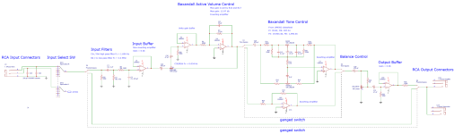
From the comments on the previous version of the schematic, it sounds like the circuit could still be improved by simplifying it. So here is a new version that has been simplified by converting the input buffer, volume control, and output buffer to single op-amp stages:

Thanks @Mark Tillotson for explaining that the dual op-amps at the output would not be necessary to drive a power amp and active sub. I have removed the second op-amp from the output buffer and converted it to a single op-amp stage.
I also removed the second op-amp from the input stage. My reasoning is that the LM4562 has low noise anyway, so there probably isn't have much to gain in terms of noise reduction. Please correct me if I'm wrong there.
I also decided to convert the Baxandall active volume control to a single op-amp active control. Will the gain setting resistors R6 and R7 still provide a max gain of ~13 db in this configuration?
Attachments
Last edited:
Does this still apply with the new schematic in post #104 (with U2 and U3 removed)?-U4, the device at the output side of the active volume control should be paralleled. The load on this op amp and U1+U2 stage become opposites at the extreme ends of pot’s wiper travel. I believe U4 will bare the brunt of the burden and face down to a couple hundred Ohms at low listening volume positions, if it works as intended. Current will be minuscule, but you may find a change in distortion profile and magnitude.
Are you saying that the DC blocking caps (C25, C24, and C26) might not be necessary? The caps on the pot wipers are still good to have right?Arguably only use ac-coupling on the input where the load impedance is known. But ensure the output DC-offset is low anyway - don't assume you'll be plugging into something ac-coupled, don't assume the source is ac-coupled...
I'd keep all of them in the layout, you always can short them out and see what happens 🙂. As a general advice, I'd suggest providing enough modification/alternative hook-up options, like making the inputs and outputs of all building blocks freely and independently accessible, as well as patch options in the building blocks themselvesAre you saying that the DC blocking caps (C25, C24, and C26) might not be necessary? The caps on the pot wipers are still good to have right?
... like that buffer in the Baxandall volume...
The max and min gains don't change, but the pot law in between will be screwed. At the center position, the pot adds 2.5kOhms to the intended 600R gain resistance, decreasing gain of the inverter block dramatically.I also decided to convert the Baxandall active volume control to a single op-amp active control. Will the gain setting resistors R6 and R7 still provide a max gain of ~13 db in this configuration?
Baxandall Volume without buffer works reasonably well when the pot's max output resistance is much lower than the gain resistor, say with a 1k pot and gain resistor of 3k or more (and accordingly, a feedback resistor of 4x the gain resistor's value, for +12dB max gain).
Yep, but the extra buffer complicates things. If used, it's probably a bit better to give it some gain and reduce it on the inverter. You thus can have two points where the output voltage can be tapped of with more freedom of setting the relative gains.Baxandall volume circuit is powerful, it allows linear pots to be used (which for stereo are usually much better matched), and it optimizes both noise and headroom at the same time.
EDIT: When the inverter gain is unity, this also gives a signal-balanced output for free.
Last edited:
Correctly. That's why studio devices have the option of only switching gain when necessary. The problem with Banxandall is that too much level regulation is forced into the pot turning range.Gain followed by attenuation = loss of headroom though. And attenuation followed by gain = higher noise floor. The Baxandall circuit avoids both
Last edited:
Ok I will probably reinstate the buffer for the volume control in the next version. That’s the way the circuit was designed anyway.
I was looking at the Bourns 91R series pots for the volume, tone, and balance controls. Anyone have any experience with these?
https://www.mouser.com/ProductDetail/Bourns/91R2A-R22-B15-B15L?qs=FKJs1C0WMKrh9n0AJFoywQ==
Another option is the Bourns 51 series, which seems very similar:
https://www.mouser.com/ProductDetail/Bourns/51ABD-B28-B15-B15L?qs=ywolDd32d79cHt2StOTdVw==
And then for twice the cost of the Bourns are the Vishay Sfernice P11A series:
https://www.mouser.com/ProductDetai...=sGAEpiMZZMtC25l1F4XBU/s9VYiqoifiE17/KfopB/g=
Can anyone with experience using these pots comment on whether the additional cost of the Vishays is worth it? Are the Bourns any good?
Ok here's the latest version of the schematic:

I returned the unity gain buffer (was U3, now is U16) to the Baxandall volume control section. I originally picked the Baxandall volume control circuit because I read (in SSAD again) that it has a linear control law that extends lower than other active circuits. I want the volume control to be silent at max attenuation, and it sounded like this one could do that.
Some people have mentioned shunt style volume controls in this thread. Can those be used with a single op-amp buffer after the potentiometer? What type of control law would that make?
I'm looking at the input section and wondering if there is anything that could be improved with the high pass and low pass filters. Right now the input high pass filter uses a 2 uF cap for C1 and a 47K resistor for R1:
View attachment 1266228
Are there any issues with using a higher value electrolytic capacitor for C1? I'm thinking about changing C1 to 47 uF and R1 to 100K, which would match the input filters of most of the other op-amps in the circuit:

This would put the input high pass filter Fc at 0.034 Hz. Is that a reasonable Fc for a preamp, or too low?
View attachment 1266228
Are there any issues with using a higher value electrolytic capacitor for C1? I'm thinking about changing C1 to 47 uF and R1 to 100K, which would match the input filters of most of the other op-amps in the circuit:
This would put the input high pass filter Fc at 0.034 Hz. Is that a reasonable Fc for a preamp, or too low?
Larger cap is OK, and if you go for a electrolytic it should be good and large (oversized) bipolar. For the lowpass, you have to consider your highest expected source impedances and if those are below 1k all is still well though 470pF is a bit on the large side of what is commonly used.
Still, I'd alway use two input cap, a small one (100pF) right at the input jack as close as possible and the second one (100pF) after the isolation resistor right at the opamp input pin.
ESD input protection is also missing, I'm typically using 24V bidirectional ESD diodes, again right at the input.
As for the output AC-coupling, when there are switched paths to the output, each path needs its own DC blocking capacitor and bleed resistor and the switch located after that, otherwise different DC offsets from the paths will cause a nasty transient.
All the pots you listed will be OK. The Bourns types are used widely and the Vishay is of reputed industrial quality. Personally, I tend to prefer larger pots, 16 or 24mm size. Larger size means longer and wider wiper track and more readily allows for multi-fingered wipers for durability. The higher power dissipation means you can user lower-valued pots (if the rest of circuit can be adapted easily, that is).
And for some possible future simplifications, if you place the balance pot as part of a small gain of the input buffer and can live with the limited range (of, say 3dB) you could have the final output right after the Baxandall tone (or its bypass inverter, resp). Baxandall Volume would then need to have a lower max gain, accordingly.
What on earth is the problem with 6 opamps? I've made a test circuit with 12 opamps in a row and it performs absolutely fine (*) - that's the whole point of low distortion audio opamps, you can use them without issue like this - old analog mixing desks had dozens of 5532's and TL072's in the signal path, absolutely fine. Contrary to the opamps-are-bad camp, if you skimp on stages you will compromise something, more opamps usually allows better performance - other than current consumption of course!
Just one poorly chosen (or counterfeit even) capacitor can be much worse than multiple opamps...
(*) https://www.diyaudio.com/community/threads/12-opamps-chained-measurements.346722/#post-6009468
Just one poorly chosen (or counterfeit even) capacitor can be much worse than multiple opamps...
(*) https://www.diyaudio.com/community/threads/12-opamps-chained-measurements.346722/#post-6009468
- Home
- Source & Line
- Analog Line Level
- Any ways to improve this LM4562 preamplifier circuit?