Ok thanks, since it sounds like a single LM4562 would be able to drive my power amp and active sub, I will probably change that output stage to a single op-amp. I'll look into the BUF634, sounds like it could be a better option than the LM4562 for that purpose.If the chosen OP is the best for cable drive is another issue to potentially be discussed: There are designs out there using much more drive capable BUF634s (which is designed for "driving work") instead and with better sound results. Maybe worth considering...
I do plan on making a tube amp at some point. I have never listened to one but I'm really interested to hear how they sound because everyone raves about them. For this project I chose to do an op-amp based amplifier because I'm familiar with building amps with chip amps and op-amp circuits are somewhat similar. A tube amp seemed like a pretty steep learning curve for where I'm at right now with audio circuit knowledge.Make a good tube preamp for that money. It will literally be a quantum leap for the sound of your audio system.
I would think that @NIXIE62 has a point of the circuit being somewhat bloated. One could squeeze out pretty much the same functionality from just two opamps per channel but of course this is DIY and @Palmtrees is free to choose whatever he'd like to do. The circuit will certainly work OK and will be a good learning exercise. Splitting things up into smaller opamp building block is a proper approach for this. At a later point one can still do something completely different.
As for opamp choices in general, I'd suggest excellent modern JFET types like OPA1642, ADA4625, OPA827, OPA828 for everything. At least for the inputs at any rate. For bipolars, I prefer OPA1602 or OPA1612 over LM4562/LM49720, besides the venerable NE5532. Placing a BUF634/LME49600 in the loop of the output opamp is a proven option but not required IMHO in any home audio system.
Anyway, good layout (I'd suggest going 4-layer, makes life so much easier at almost no cost penalty these days) and a good supply etc IMHO is often more important than circuit/part choices. As is system wiring, which looks like being unbalanced all the way. A differential (balanced) input option for the preamp could be a very effective way to mitigate any ground noise issues, just in case.

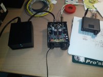
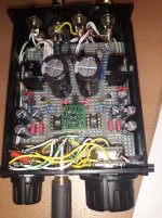
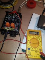
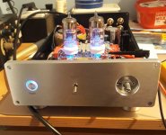
Here is my little test preamplifier with a separate power supply. It serves me occasionally as a headphones amplifier and for measuring and testing various OPAs (dual and single). It has two inputs, balance and volume control, mute circuit at the output and selectable gain (3-11x). Everything is DC coupled, the schematic is the simplest possible, non inverting amplifier. Cheap, simple and great sounding.
Attachments
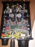
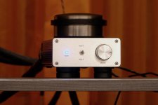
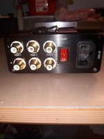
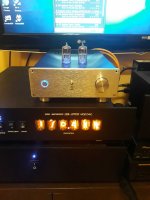
Here is another similar preamp with OPA, only in a slightly nicer box and without balance controll. So you know I don't always use tubes. Sometimes I listen to this too, for a change. Especially when I get an OPA that I haven't had a chance to listen to before.
I've never had the chance to try the LM4562, but I have the LME49720 and I wouldn't recommend it. They are the same OPA, just different markings as far as I know.
I've never had the chance to try the LM4562, but I have the LME49720 and I wouldn't recommend it. They are the same OPA, just different markings as far as I know.
Attachments

Last edited:
Hi Palmtrees,
Just some observations:
-Regarding your subwoofer output, consider introducing a secondary path having a unity buffer at junction S1. This provision will serve as a dedicated secondary output (subwoofer) that remains controlled by the master volume. While the LM4562 is very capable, the input impedance of your sub amp and stereo power amp will likely be different. When you are laying out the PCB, you could even provide pads for feedback resistors if you need some gain. To get unity, a bent wire lead cut from a resistor will provide the necessary path while leaving the gain as a future option. You can also add a buffer and sum L+R to a single mono output if you wish.
-U4, the device at the output side of the active volume control should be paralleled. The load on this op amp and U1+U2 stage become opposites at the extreme ends of pot’s wiper travel. I believe U4 will bare the brunt of the burden and face down to a couple hundred Ohms at low listening volume positions, if it works as intended. Current will be minuscule, but you may find a change in distortion profile and magnitude.
This type of volume control can also be an annoyance. Firstly, if the potentiometer’s wiper loses contact with the track there will be a nuclear blast of max volume audio at the output equal to the earlier unity stage, because it’s a subtractive volume control which superimposes an inverted signal upon a non-inverted one.
Secondly, the active volume control may not provide good control over listening levels early in the pot rotation (low levels) and this is the usual complaint. I think you’ll prefer a traditional arrangement with the bottom of the pot’s track at audio ground potential. If active is the preferred method, I had posted an alternative active circuit in another thread, so it might be worth modelling and experimentation.
-You may also wish to place the entire volume circuit at the output of the pre just before a final buffer stage. This way, all forward op amps’ noise is attenuated according to the volume pot’s track position. If so, also move the subwoofer unity stage accordingly.
Just some ideas.
Last edited:
Not always a good idea. You need to protect the circuit from high input levels so as not to cause distortion. Depends on the use case. The issue of noise reduction through the pot only arises if the previous circuit is poorly designed or has to much gain.-You may also wish to place the entire volume circuit at the output of the pre just before a final buffer stage. This way, all forward op amps’ noise is attenuated according to the volume pot’s track position. If so, also move the subwoofer unity stage accordingly.
His design has a stage prior to the volume control already, so if it’s going to clip nothing will stop that as it is. I’m not disagreeing, but check his schematic.
I don't think 21 steps are enough to make a reasonable volume adjustment.
21 steps is enough for me. This sounds better than Alps Blue Velvet to me, and the channel balance is perfect. There is also a more expensive version with higher quality resistors, but I haven't tried it.
https://www.audiophonics.fr/en/comp...ted-axis-cms-resistor-50kohm-log-p-11226.html
I have this one in the tube buffer. It replaced the ALPS RK27. It's not exactly a 1:1 replacement, the thread on the ALPS is a little smaller in diameter, the opening has to be widened. Of course, I did not use the loudness pin. That pin is pulled out in the middle of the resistive path.
I have this one in the tube buffer. It replaced the ALPS RK27. It's not exactly a 1:1 replacement, the thread on the ALPS is a little smaller in diameter, the opening has to be widened. Of course, I did not use the loudness pin. That pin is pulled out in the middle of the resistive path.
Last edited:
When designing a preamplifier with too much gain, the potentiometer is usually used only in the initial part, up to 25-30%. When designed properly, then 50-75% of the rotation angle is used and everything is ok with 21 steps. It is also important how the potentiometer regulation curve is derived. Some are better, some worse in that sense.
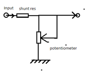
Sometimes a better sound result is obtained with a potentiometer connected as a shunt regulator. In that case, the potentiometer is not in the signal path. There is a danger that in case of loss of connection between the slider and the resistive layer, the full output voltage is obtained at the output. The shunt potentiometer also divides the input voltage, so the output is that much lower.
Sometimes a better sound result is obtained with a potentiometer connected as a shunt regulator. In that case, the potentiometer is not in the signal path. There is a danger that in case of loss of connection between the slider and the resistive layer, the full output voltage is obtained at the output. The shunt potentiometer also divides the input voltage, so the output is that much lower.
Last edited:
If it is not in the signal path, how could it have any effect at all? And, are you aware that a potentiometer already contains a shunt path as well as a series path? Nothing is gained by discarding the internal series pathand using an external one. It might even add extra distortion...Sometimes a better sound result is obtained with a potentiometer connected as a shunt regulator. In that case, the potentiometer is not in the signal path. There is a danger that in case of loss of connection between the slider and the resistive layer, the full output voltage is obtained at the output. The shunt potentiometer also divides the input voltage, so the output is that much lower.
Such a configuration is sometimes considered advantageous for having a fixed resistor at signal path. The effect of the potentiometer to sound is still there, but should be less than standard configuration. I am of course against that schematic because it is a danger for the output amplifier and speakers. I tried it out of pure curiosity, I didn't notice any significant difference in the sound, and went back to the standard schematic.
Attachments
As far as I understand, if I use JFETs for everything then the DC blocking caps on the pots would no longer be needed. Is that correct?As for opamp choices in general, I'd suggest excellent modern JFET types like OPA1642, ADA4625, OPA827, OPA828 for everything.
Where did you get the chassis from? It looks similar to the ones offered by modushop.biz. I have the Galaxy 2U from them for my power amp, will probably go with the Galaxy 1U for the preamp, I like the slim profile of it which will look good on top of my power amp:Here is another similar preamp with OPA, only in a slightly nicer box
https://modushop.biz/site/index.php?route=product/product&path=33_287_289&product_id=265
Was it Ali or Ebay, I don't remember. The text is laser engraved later. Modushop is better of course.Where did you get the chassis from?
Last edited:
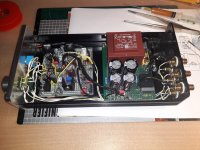
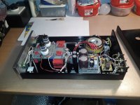
Depending on the complexity of the device, you will need a much larger box. This is the tube buffer for my sister. (Aikido cathode follower with 5670/6N3P/6CC42 tubes). This buffer drives the output amplifier and the active subwoofer line inputs. There are also larger boxes just for preamplifiers, completely drilled and with text, take a look at Aliexpress/eBay.
Attachments
Last edited:
Like this for example.
https://www.ebay.com/itm/374671270180
https://www.ebay.com/itm/374732588814
In principle, the boxes themselves are not expensive, but the postage kills. Whatever I'm making, it's always a pain to find the box and pack the electronics in it.
https://www.ebay.com/itm/374671270180
https://www.ebay.com/itm/374732588814
In principle, the boxes themselves are not expensive, but the postage kills. Whatever I'm making, it's always a pain to find the box and pack the electronics in it.
Last edited:
- Home
- Source & Line
- Analog Line Level
- Any ways to improve this LM4562 preamplifier circuit?