Is this how you would connect the RF filtering caps?Add another ceramic 220pF directly on the input connectors to stop RF getting into the case too, LM4562's are very sensitive to RF. Ceramic caps must be C0G/NP0
Or would the cap connect directly between the L and R channels?
Thank you @chip_mk , @MarcelvdG , @Mark Tillotson and everyone else for your suggestions and explanations. I just finished a version 2 of the schematic based on your input. The circuit is greatly simplified, which is awesome. Please let me know if anything else is missing, or could be improved.

I decided to leave the parallel input buffer and series output buffer in this version because I'm still not sure if there is a benefit for those or not. For the output buffer, I will be driving two devices, a power amp and an active subwoofer (line in). Would a single op-amp at the output be enough to drive that? For the parallel input buffer, is the additional cost and complexity of two op-amps worth it in terms of noise reduction?
I decided to leave the parallel input buffer and series output buffer in this version because I'm still not sure if there is a benefit for those or not. For the output buffer, I will be driving two devices, a power amp and an active subwoofer (line in). Would a single op-amp at the output be enough to drive that? For the parallel input buffer, is the additional cost and complexity of two op-amps worth it in terms of noise reduction?
How do you like your tone control? Have you noticed any issues using lower value pots and resistors? What are the frequency cutoffs? The tone control in my circuit is from the LM4562 datasheet but I recalculated all of the component values so I could use lower value pots and different cutoff frequencies. My cutoffs are Fl=40 Hz, Flb=498 Hz, Fh=19,904 Hz, and Fhb=1,990 Hz. Not sure if these are good values to use though. I'm interested to know what people think are good Baxandall tone control cutoff values since most sources on the internet say different things.This is part of what I have using
My intent with R1 and C2 was to have a low pass filter to set the upper limit of the amplifier's bandwidth to filter out any interference above the audible range. With R1=100R and C2=15 nF, the Fc of the low pass filter is 106 kHz. But if I change C2 to 470 pF the Fc increases to ~3.4MHz. Is that an acceptable upper frequency cutoff for a preamp? Or should I increase the value of R1 to bring the Fc down closer to 100 kHz?C2 is too big and will act as low pass filter for a high impedance source - 1nF is plenty, 470pF is probably a good general value.
Just use this with a decent 5V linear supply, can likely hide it inside your amp case.
Is a Bluetooth 5.0 board that uses a 32 bit processor and costs next to nothing. The large capacitors are output coupling and can be bypassed, replaced if needed but are actually decent sounding…
Make tone changes if you really need to within your iPhone.

I have one in an ancient Phase Linear chassis that has a Tomlinson Holman amp board, isolation transformer/line filter inside for casual listening.
Is a Bluetooth 5.0 board that uses a 32 bit processor and costs next to nothing. The large capacitors are output coupling and can be bypassed, replaced if needed but are actually decent sounding…
Make tone changes if you really need to within your iPhone.
I have one in an ancient Phase Linear chassis that has a Tomlinson Holman amp board, isolation transformer/line filter inside for casual listening.
You have shorted caps in the output buffer amp feedback loops. Seems redundant
The bypass switch won't work in this setup as the op amp will zero out the signal at its output as no input is applied.
The bypass switch won't work in this setup as the op amp will zero out the signal at its output as no input is applied.
Last edited:
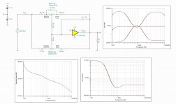
Hi, take a look at simulation result! Gain is +-15db on that bass/treble tone control, to be honest an nice tone control. The only one fine modification on real circuit is you need to change 22nF by your taste, I put there 10nF to get not that agresive high freq, got realy relax highs using 10nF, but I will fine tune it with capacitors value between 10nF and 15nF, this time Vishay capacitors MKP1839 booth for treble and bass (c6, c7, c8). As you can see from simulation an nice bandaxal.How do you like your tone control? Have you noticed any issues using lower value pots and resistors? What are the frequency cutoffs? The tone control in my circuit is from the LM4562 datasheet but I recalculated all of the component values so I could use lower value pots and different cutoff frequencies. My cutoffs are Fl=40 Hz, Flb=498 Hz, Fh=19,904 Hz, and Fhb=1,990 Hz. Not sure if these are good values to use though. I'm interested to know what people think are good Baxandall tone control cutoff values since most sources on the internet say different things.
I recommend you an simulation program, for example TinaTI from Texas Instruments,use , it have a lot of opamps spice models (e.g. https://www.ti.com/product/OPA1656#design-development) and try simulate your circuit, its the best thing to do and learn before any real circuit!
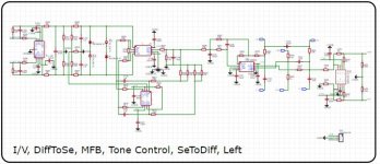
Picture 2 is my personal circuit, dc coupled, dc servo, and is blured sorry, shows an example.
Attachments
Last edited:
What would be a good way to bypass the entire preamp and tone controls? Could I just use a dual pole switch to switch off the path back to the op-amp? Is there a better way?You have shorted caps in the output buffer amp feedback loops. Seems redundant
The bypass switch won't work in this setup as the op amp will zero out the signal at its output as no input is applied.
A selector switch to connect left side of C17 to either output of U7 or output of U4 (bypass position). I.e. to select what to feed to the output stage: from the output of TC or from the stage preceding TC.
If you keep this solution of active volume control with two opamps then I would change my previous recommendation to ommit R5 in ver 1. You can reintroduce it perhaps as 100k res. The reason is that pots can be unreiable and the sliding contact (midle contact) can disconnect intermittently. In such event voltage on + node of U3 will be udefined and could cause dangerous thump. R5 = 100k would significantly mitigate it.
Correct only if the signal source has 0 output impedance. But what if your player has 400ohm (not unrealistic)? Then Fc becomes 20kHz. That is -3dB on 20kHz!My intent with R1 and C2 was to have a low pass filter to set the upper limit of the amplifier's bandwidth to filter out any interference above the audible range. With R1=100R and C2=15 nF, the Fc of the low pass filter is 106 kHz.
Next to consider is that signal source and power amp also have some HF filters. Each of them could introduce few tenths of dB loss in audio band. Cumulative result could be noticable.
But ultimately you should decide by listening which value is best compromise. From experience, it is typically 0.1 - 1nF.
Same concern goes for U7 and Bass pot as it's the only DC feedback path. I would recommend paralleling C12 and C14 with 220k resistors that woud maintain DC FB path in case of Bass potentiometer failure. Impact on TC characteristic would be neglectable.If you keep this solution of active volume control with two opamps then I would change my previous recommendation to ommit R5 in ver 1. You can reintroduce it perhaps as 100k res. The reason is that pots can be unreiable and the sliding contact (midle contact) can disconnect intermittently. In such event voltage on + node of U3 will be udefined and could cause dangerous thump. R5 = 100k would significantly mitigate it.

I see now that in the v2 schematic the signal would make it to the inverting inputs of U10 and U11 when the bypass is switched on.A selector switch to connect left side of C17 to either output of U7 or output of U4 (bypass position). I.e. to select what to feed to the output stage: from the output of TC or from the stage preceding TC
I was kind of hoping to have a bypass switch that would bypass the whole preamp, without going through any of the op-amp stages. I like the idea of being able to switch back and forth to compare the effects of the preamp to the raw signal into the power amp.
Do you think there would be any issues with using a dual pole switch (4 pole for stereo) that switches the input before C1 and the output after R25 at the same time? I’m considering doing the same for the tone control circuit unless there is a better way.
Directly to ground always for RF suppression.Is this how you would connect the RF filtering caps?
View attachment 1260658
Or would the cap connect directly between the L and R channels?
Just finished version 3... Thanks @chip_mk, I added the 100K and 220K resistors to bypass DC.

One thing I'm concerned about now is the 470 uF DC blocking caps before the potentiometers (C24, C25, and C26). That capacitance will require electrolytics, but I have always heard that it's best to avoid electrolytics in the signal path. Does that actually matter and if so are there any other options to use smaller capacitance film caps there?
One thing I'm concerned about now is the 470 uF DC blocking caps before the potentiometers (C24, C25, and C26). That capacitance will require electrolytics, but I have always heard that it's best to avoid electrolytics in the signal path. Does that actually matter and if so are there any other options to use smaller capacitance film caps there?
I think I'm okay with that since I can always just bypass the tone control to get volume and balance only. All of my sources (iPhone, TV, CD player) have volume controls on them, so I can still adjust the volume when the bypass is turned on.You lose volume contol in that case.
The volume control should be able drive the tone control as its output is an opamp output directly.
DC-blocking with electrolytics is OK if the signal voltage across the electrolytic is tiny - ie use a large electrolytic with a cutoff frequency thats in the range 0.1Hz to 1Hz will typically do the job. The alternative would be a DC servo stage.
DC-blocking with electrolytics is OK if the signal voltage across the electrolytic is tiny - ie use a large electrolytic with a cutoff frequency thats in the range 0.1Hz to 1Hz will typically do the job. The alternative would be a DC servo stage.
- Home
- Source & Line
- Analog Line Level
- Any ways to improve this LM4562 preamplifier circuit?