Hello
Any opinions and suggestions about this tda7294 circuit ?
#▷ 200W Simple audio amplifier circuit using tda7294 — Circuit Wiring Diagrams
Thank
Bye
Gaetan
Any opinions and suggestions about this tda7294 circuit ?
#▷ 200W Simple audio amplifier circuit using tda7294 — Circuit Wiring Diagrams
Thank
Bye
Gaetan
Attachments
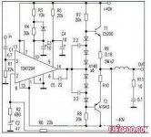
Doesn't look as though the discrete output stage biassing arrangements were given much thought.
R7 provides about 2mA of bias current but the typical Hfe of the 2SC5200 will be around 100 so the current limit looks to be around 200mA. But with say 1.8V across the top half of the diode string there will be about 1.2V across the 0.18ohm which is a quiescent output stage current of 7A - but this can't be provided due to the lack of bias.
Looks broken to me.
Rises a ton o eyebrows, doubt it was ever built by anybody.
1) there's not enough current to drive any bipolars.
2) It's way overbiased, you need around 1 diode drop to bias a bipolar
3) in the same phrase mentions bipolars and mosfets as if they were the same or close equivalente
4) 200W into *what* load?
+/-40V rails amount to about 60W@8 ohms and 100W@4v ohms .
And that if power transistors are properly driven, these are not.
In theory if it were setup correctly and care taken with output stage swing +-40V can do 200W into 4 ohms. However the rest of the comments above questioning wether the circuit acually would work at all are quite correct. There are application circuits in the ST data sheet for up to 100W into 4R load but I beleive it is better to do such powerful amplifiers (greater than ~ 100W) in discrete components as having input circuits on same die as hot running output devices is never a good idea.....what the original circuit may have been trying to avoid, albeit flawed.....
http://www.st.com/web/en/resource/technical/document/datasheet/CD00000017.pdf
http://www.st.com/web/en/resource/technical/document/datasheet/CD00000017.pdf
Last edited:
In short there are better ways of doing 200W into 4R and we wouldn't touch that circuit with a bargepole. Indeed the person who published it ought to be....
Gaetan,
select some projects for a 200W into 4ohms amplifier from this Forum.
Throw away any that do not have adequate build details.
Throw away any that do not have successful copies made by other Members.
Throw away any that misbehave under testing.
You should be left with around a dozen of good buildable amplifiers recommended by other Members.
Select one and build a mono version to test.
Hello
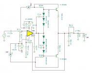
I have simulated a similar circuit with Tina-Ti, using a LM3886.
At leat on simulation, it's work ok.
I did use TIP3055 and TIP2955 just for the simulation.
Here it is.
Thank
Bye
Gaetan
I have simulated a similar circuit with Tina-Ti, using a LM3886.
At leat on simulation, it's work ok.
I did use TIP3055 and TIP2955 just for the simulation.
Here it is.
Thank
Bye
Gaetan
Attachments
Last edited:
Have a look at my TDA7293 parallel thread. It is a bit more straightforward. It can do 130W to 4R. And the rather tame clipping pattern (if modded as described) is competitive when it comes to useful decibels output from a real speaker in real use.
Triple parallel version can drive a 2 ohm load to a bit over 200W (if music signal and also a plentiful power supply).
Due to voltage limitations of the chips, you're not going to get more power, so you might as well not have the inconvenience of adding an output buffer.
Triple parallel version can drive a 2 ohm load to a bit over 200W (if music signal and also a plentiful power supply).
Due to voltage limitations of the chips, you're not going to get more power, so you might as well not have the inconvenience of adding an output buffer.
- Status
- Not open for further replies.
- Home
- Amplifiers
- Chip Amps
- Any opinions and suggestions about this tda7294 circuit ?