
See the AC input? Three terminals for the transformer center tapped wiring, and the center one is ground.
Last edited:
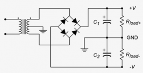
Schematic below shows how it works.
If your transformer does not have a centre-tapped secondary but has two identical secondaries, they can be connected to behave as a centre-tapped secondary. You just need to make sure that phasing of the two secondaries are correct.
If your transformer does not have a centre-tapped secondary but has two identical secondaries, they can be connected to behave as a centre-tapped secondary. You just need to make sure that phasing of the two secondaries are correct.
Attachments
Schematic below shows how it works.
If your transformer does not have a centre-tapped secondary but has two identical secondaries, they can be connected to behave as a centre-tapped secondary. You just need to make sure that phasing of the two secondaries are correct.
tying yellow and black and this becomes my center-tap ground. right? Thanks again

This works by using half wave rectification from each segment of the secondary. By "segment" understand a contact from one end to the centre tap of the secondary. Halve wave rectification allows the capacitors to be charged such that the voltages act in series resulting in double the voltage from one coil. Full wave rectification is achieved by having two other diodes which make use of the previously unused AC half cycles.
tying yellow and black and this becomes my center-tap ground. right? Thanks again
View attachment 1091764
Yes, yellow/black for centre-tap.
- Home
- Amplifiers
- Power Supplies
- any ideas how it was able to get a V+ and V- using 1 bridge rectifier?