@ Bjosephs.
Knowing what you need makes it solvable.
To begin with, and I'm adding this after seeing your schematic:
personal opinion, you have way too much NFB which brings 2 problems:
a) stability.
I'm amazed your amp is neither unstable nor plain oscillating.
This does not appear in simulations, of course, but on real Word stuff.
Please load it with a real speaker and tell us.
Also sweep and scope it, to see that sinewaves stay so without undue "add ons".
b) sensitivity.
You have 100% NFB which means input signal must be the exact same value as the speaker driving voltage, a very tall order, and (barely) achievable here only because your power output is modest.
If you lowered NFB by a mere 6dB (which still is plenty, by Tube amp standards) , you'd need a much easier to swallow ~3V RMS .
Back to your questions:
You have 2 ways to work with a single supply pulled from +V
1) Op Amps .
You have 285V +V
You need +30VDC
A TL072 dual Op Amp (I guess your amp is Stereo) needs ~3mA total
Aim for 5mA available through a resistor, add a 27V 1W Zener in parallel with Op Amp both to kill residual ripple and to take the excess current.
So you need a resistor= 51k (you may also use 47k)
Dissipation: 1.4W so choose anything from 2W to 5W .
Such an Op Amp will be very transparent, wideband, distortion is negligible, noise is not a problem there and costs less than $1 .
No need for a custom PCB, you can easily build it on Vero or perfboard.
2) FETs
You can use standard FETs, conceptually closer to Tubes (in practice and in this use somewhat irrelevant) , you may build 1 stage per channel, aim for ~1mA current for each stage for practical reasons, feed them from +25V which most can stand up to +40V, a few do.
Main problem is spread, you may have to buy 10 to find 2 "reasonably" matched.
Hope this helps.
A very workable alternative could be a simple AC coupled opamp stage resistively fed from the main HT line together with a simple zener stabiliser. You should be able to get away with a single 5 watt or couple of 2.5 watt series feed resistors.
Ya, I'm not a fan of zener regulators... just don't trust them. If I were game for using the HT tap to power the opamps there are linear regulators that I'd go to first. If I go the opamp route they are getting their own supply rails at this point.
interstage signal transformer?
It's funny you mention that, I had been thinking on the possibility of an input transformer with a step up ratio. Unfortunately SIGNIFICANT ratios are hard to come by in high quality units made for line level sources, there are several 1:1.4's in the Jensen line. A mic transformer would have a good ratio but certainly not appropriate for line level work. Lundalhl makes one that looks like good (1:4 ratio, +20dbu) but it would be close to $300 for the pair. I moved on from that idea for now...
So the power amp needs 10Vp-p for full output swing. That is simply a bad design. An amplifier should ..eh.. amplify...Anyway it should amplifly a line signal enough for full output swing. This design does not. A problem is best solved at its root.
I appreciate the help so far but I think this is a bit unfair. This is an interesting approach that uses the secondary to provide degenerative cathode feedback that essentially turns the output stage into a unity-gain current amplifier - a "buffer" with unusually low output impedance for a Pentode (proposed in an article by the same guru that you linked to on the opamp>el84 circuit, John Broskie). It's cool and it works and it sounds great, he just needs a little help with the signal strength 🙂. Many high quality tube amps used cathode feedback - albeit with custom transformers and windings - and virtually all but the most simple amps use more than one gain stage to balance linearizing feedback while maintaining necessary voltage gain. Determining what that stage is going to be is where I'm at now, since the output stage is performing as intended.
a) stability.
JMFahey, it's actually been up and running all week with no issues, 23db of feedback and all. I've been listening for days and tapping wires waiting for something to go wrong (You saw the pictures 😱), scope signal on a sign wave is clean from 20 to 40k. Square wave rings a bit but I figured I could trouble shoot that later after all the wires are in their final resting places.
If you lowered NFB by a mere 6dB (which still is plenty, by Tube amp standards) , you'd need a much easier to swallow ~3V RMS .
Good point. If all else fails I think I can achieve something close to this by using the 4ohm tap rather than the 8 for the cathode feedback.
2) FETs
You can use standard FETs, conceptually closer to Tubes (in practice and in this use somewhat irrelevant) , you may build 1 stage per channel, aim for ~1mA current for each stage for practical reasons, feed them from +25V which most can stand up to +40V, a few do.
Actually they come in "tube" voltage too, LND150 specifically. It can sit in for a triode with the same component values in some cases. They too need to be reigned in with feedback though to reduce distortion - at least in simulation they perform more poorly than simply using another ECC99 stage. Unfortunately, without a distortion analyzer I'm forced to let simulation point me in a reasonable direction (or at least away from the worst directions) and let me scope and ears do the rest.
Brian
yup 3 stages and not enough CL gain > sumting wrong
rethink NF strategy
There are 2 stages, a preamp tube "in loop" and a power tube. A TBD third stage, solid state or otherwise, is more than sufficient for full output.
In truth I'm being greedy as the output of my Ipod already drives this thing to a "normal" listening level by itself. In some parallel universe I've already boxed this thing up and moved on. 🙄
We aren't in the tube forum so I'd rather not discuss the particulars of the core design here, not fair to future readers. I linked to my other thread in an earlier post if anyone wants to discuss the pros/cons of the output stage there. Thanks to everyone for helping me vet out the possibility of using the switching regulator as a shortcut to a bipolar supply.
Brian
Last edited:
"able to get away with"... ----> We better design stuff well and swim against the stream.
This is the worst plan ever to feed opamps. Suppose what happens when the Zener diode breaks down... Outright dangerous !!!!
Dangerous. How so ? You would design the opamp stage to be in keeping with the valve philosophy. AC coupled at the input using a small 0.22 or thereabouts 400 v cap. Where is the safety hazard ?
And why would a correctly specced zener be likely to fail ?
Resorting to a complex second PSU to feed a single opamp is bad engineering in the extreme imo 🙂D) when such a simple and workable alternative exists.
(and JMFaheys suggestion of the TL072 is actually a very good choice. Mention of the TL0 series around here usually sees your credibility fly out of the window but its a top choice for something like this. Used correctly and its a darned good device)
If the Zener diode breaks down full B+ voltage will be on the opamp. Why do parts fail ? Why do humans die ? I don't know. The question in good engineering is not "why" but "when" and "what if". Secondly the heat coming from the 5W resistor is not very "eco 2016" and it will also have a definite lifetime. Tubes already relatively use a lot of power so why burn more Watts than necessary ? Thirdly there is another failure possibility as parts that get hot will be a risk.
A complex PSU ? Using a standard well designed 2 x 12V PSU with opamps is ..eh...minimal standard in engineering. In third world countries they might connect opamps with a 5W resistor to B+ and use a noisy Zener diode with all the added risks and save a few pennies. The capacitor that is needed over the Zener might also be omitted to make it cheaper. I could also suggest to leave out the power transformer and connect the amp directly to mains. Why use a transformer when 240 V AC is around....Sometimes too simple simply is too simple. "Getting away with it" is downright opposite to the goals of many of this forum. We see a lot of engineering solutions in ready made stuff where designers "got away with it". Better do things right when DIYing as it will be more expensive than ready build stuff anyway.
Suggesting TL072 when many modern, better and cheap opamps are out there..... I see tube guys are conservative. When they finally and reluctantly accept a semiconductor they keep using it for decades, probably because it works like this with tubes where no new types are developed since, let's say, 30 years. I guess LM4562 will be in fashion in a year or 10 🙂
Last edited:
We will have to agree to disagree on this one Jean.
I believe physical space (it mustn't take up much room) was one of the main requirements also. I would take the shunt zener supply anytime in a situation like this. Correctly designed and with suitable parts its a sensible (and safe) solution.
The idea is out there anyhow 🙂
I believe physical space (it mustn't take up much room) was one of the main requirements also. I would take the shunt zener supply anytime in a situation like this. Correctly designed and with suitable parts its a sensible (and safe) solution.
The idea is out there anyhow 🙂
Let's agree to disagree but with all known information most suggested solutions seem like carrying water to the sea. The main problem is a power amp that does not amplify enough. It needs 10 V p-p for input voltage while standard line level voltage is 2V for some decades now....problems are better solved at the root as it is most simple and reliable. All other solutions mean deviating from standards or they're a kind of artificial engineering.
It's a bit like designing a car with a hyper eco engine that produces a tiny 10 HP. Colleague engineers laugh at you and tell you the engine is too light but you are confident. It is very fuel efficient but acceleration is 120 seconds from 0 to 80 km/h. Now you will be solving this by adding solar cells on the roof and electric motors on the wheels. Now steering becomes difficult so you need to find a solution for that. Aha, power steering it will be but the necessary pump needs 1 HP of your total available power. Now you need to find a way to have more power. Etc. etc....It might have been better to design with an engine that has enough HP to drive the car in worst case conditions and being fuel efficient at that.
Creating a low voltage by tapping the B+ with a hefty resistor and a Zener diode is simply bad engineering (coming from an era that no other solutions were available). I can not believe some really would choose this nowadays with many standard solutions being cheap, small and reliable. If the Zener fails it will go out will a loud bang for sure possibly also giving a few hundred Volts pulse via the opamps input caps to the preceding equipment like a CD player that will also die. I am diappointed that you, as a mod, condone this type of engineering.
Last edited:
I am diappointed that you, as a mod, condone this type of engineering.
I'm only a mod when wearing the
 hat. You know that better than anyone. Not wearing the hat and I'm free to express my opinion of how I would approach something.
Here, and I'm just an ordinary member suggesting how I would approach powering a low power opamp when all we had readily available was a high HT rail. The suggestion is entirely in keeping with a valve amp (that's any valve amp) that has no pretension to thermal efficiency or energy usage.
Zeners don't go bang when fed from a current limited source (HT plus series resistor) should they fail. Typical failure mode for a zener is for it to become leaky and pull the voltage lower but that can not be relied upon as a safety feature. The input coupling cap must be suitably rated to withstand the full HT if that scenario were to appear.
In the past I have seen many a Zener going bad by becoming an "open" device. If that happens in the solution you gave full B+ (let's say 250 V ) will be on the opamp. Boom !
If the Zener diode dies by becoming a short...again 250 V on the Zener and opamp...Boom !
In the end results of destruction will be more or less the same. This whole thing could have been avoided by not choosing it at all. There are many ways to solve this safe and sound with better quality of voltage and less heat and noise too.
I am sorry but I have to report your post with that suggestion as it is dangerous practice and totally unnecesary as well. Audio wise it is a bad idea too with only an asymmetrical voltage available and power supplied by a noisy zener.
Last edited:
Jean.
If the zener were open circuit then it would be 250 volts current limited by the series resistor. For the TL072 that got mentioned we are looking at say 8 to 10 milliamps as a maximum of available current should the zener become open circuit. That current would not cause a zener to physically go pop or boom. A suitably specified input coupling cap removes any user risk in that situation anyway.
We can always say what if/ what if ad infinitum. What if the first valve stage developed an anode/grid short or there was a flashover. Does that not put the user at risk in the majority of valve designs ?
What if our Class X or Class Y caps developed a problem.
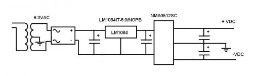
I believe this is the solution you are looking for.
The LM1084 is a suggestion...use a low dropout regulator because you do not have too much headroom from a 6.3V supply.
I have used this for automotive where the supply is not within 10.8-13.2V so an NMA1212SC was not an option. A LM7805 type was used in that case...had the headroom.
Some DC-DC converters require a minimum load. I believe this one does.
Put in a resistor/LED as a minimum load. This also tells you the supply is on.
If you want +/-15V use a NMA0515SC. NMA0515SC Murata Power Solutions Inc. | Power Supplies - Board Mount | DigiKey
Have fun.
🙂
Attachments
Last edited:
I believe this is the solution you are looking for.
The LM1084 is a suggestion...use a low dropout regulator because you do not have too much headroom from a 6.3V supply.
I have used this for automotive where the supply is not within 10.8-13.2V so an NMA1212SC was not an option. A LM7805 type was used in that case...had the headroom.
Some DC-DC converters require a minimum load. I believe this one does.
Put in a resistor/LED as a minimum load. This also tells you the supply is on.
If you want +/-15V use a NMA0515SC. NMA0515SC Murata Power Solutions Inc. | Power Supplies - Board Mount | DigiKey
Have fun.
🙂
DUG, thanks for contributing. In your schematic you are providing the 5vDC input with what would actually be +/-2.5vDC because of the grounded center-tap. Is that actually an option? I hadn't considered that. I guess because the converter is isolated it doesn't care if the input is 0V/5V, -2.5V/2.4V, or 5V/10V - essentially just the potential between the pins matters, within reason?
Thanks!
...
because the converter is isolated it doesn't care if the input is 0V/5V, -2.5V/2.4V, or 5V/10V - essentially just the potential between the pins matters, within reason?
Thanks!
yes
- Status
- Not open for further replies.
- Home
- Amplifiers
- Solid State
- Any experience powering opamps from DC-DC converter?