Of course you can.Any crazy idea?
Is possible build an all darlington power amplifier?
And you can even go crazier than that: here is a JLH amplifier built purely from voltage regulators:
http://www.diyaudio.com/forums/chip-amps/176052-now-regulator-chip-jlh-amp.html
And this is the current crazy project:
http://www.diyaudio.com/forums/chip-amps/193214-class-chip-amp-now-complementary-version.html
http://www.diyaudio.com/forums/headphone-systems/159202-jlh-headphone-amp.html#post2071337
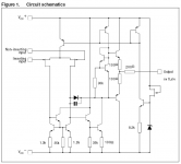
JLH with 74LS04 Logic Gate
JLH with 74LS04 Logic Gate
That's a really nice one!http://www.diyaudio.com/forums/headphone-systems/159202-jlh-headphone-amp.html#post2071337
JLH with 74LS04 Logic Gate
I missed it at the time, but I utterly enjoy it now.
Power to the loonies!!!!
Here's another one.
I tried to go a bit simpler than Douglas Self with his NE5532-build and hooked up 12 TL074 in parallel, which is 48 single OP amps. The internal circuit looks promising: FET inputs which should be easily paralleled an built-in 200R current sharing resistors at the outputs. I put this thing together on perfboard and powered it with two SMPS-type wall warts.
It actually worked, but not as good as I was hoping for 😱. I used an el-cheapo speaker box for testing and it played music, nice and clean with no audible noises. The scope showed no signs of oscillation or something else, output offset was a couple of millivolts, seemed fine. But the chips got quite warm while in "standby". I don't know how high the quiescent current was, since I don't have a +- Lab supply at hand and was too lazy to hook an ammeter into one of the power lines 😀, but it must have been a bit more than what's stated in the datasheet. Playing only silent music, those tiny bastards became bloody hot. I had to put the whole thing on a heatsink beacuse I was afraid they could unsolder themselves 🙄.
According to the maximum dissipation and current output capability of the chips they should be able to hande an 8 Ohm load with ease, but I guess they were rather occupied by fighting themselves...
Attachments
A voltage regulator is an amplifier with fb loop ect. There is no reason you can't use Darlingtons. You can skip the driver stage.🙂 The thing about Darlington outputs is the thermal feedback loop needs to be as short as possible, or maybe a feedback pair output stage?😕
- Status
- Not open for further replies.