I must admit this answer is confusing me. Can you detail please?Generally a voltage input is high-Z (though not required), a current input is low-Z (though not required)
It is possible that you do not speak about Z_source but about Z_in?
If yes, then should we not match these impedances at the input terminals?
For example: the particular case of current source (high Z by definition) is usually handled by high Z_in devices, like FETs for example. Am I wrong?
If the input is talked about, it means input impedance, if the source is talked about, its source impedance,
there are 4 impedances for an amp stage: source, input, output, load
For audio source << input, output << load, for RF, source = input, output = load.
A current input is sensing current, typically using an IV conversion stage, the usual sort of these is low input impedance (virtual ground).
there are 4 impedances for an amp stage: source, input, output, load
For audio source << input, output << load, for RF, source = input, output = load.
A current input is sensing current, typically using an IV conversion stage, the usual sort of these is low input impedance (virtual ground).
Hi Ionmw,
This a is fascinating topic for me on so many fronts. Ironically, I've owned an A77 since circa 1970, but haven't used it in at least 40 years. I also have the service manual, though I'm not sure I'll ever find it. I didn't know that its tape-head preamp was a TIA, though that seems to make sense--- I think it would extend bandwidth by having the tape-head loaded by a virtual short circuit. If you can post a schematic, I'd love to look at it.
On another front, I've designed TIAs for a low-noise photodiode application that spanned from about 50kHz to 30MHz. So maybe I can clarify on some aspects, drawn from my photodiode TIA experience.
TIAs often use a FET at the input because bias-current noise from the input transistor is often a very important performance limiter; the bias current from a bipolar transistor is source of shot noise and makes them less attractive. But voltage noise from the input transistor is also problematic, worsened by the shunt capacitance of the photodiode. A complex topic.
So the input device of a TIA has high impedance, but is followed by large gain and by feedback resistance (Rf) back to the input; it's the large open-loop gain, driving the feedback Rf, that gives the low virtual input impedance seen at the input of the TIA circuit. It's very much analogous to the "virtual ground" concept in opamp circuits.
Noise figure is another complex topic. The concept of impedance matching of source and load is most often used in maximizing power transfer or in properly matching RF transmission line characteristic impedance, eg. 50 ohm, 75 ohm, etc. In low noise transistor data sheets, you'll often see info pertaining to "noise match" which is design for best noise performance, in contrast with "maximum available gain", etc. Best noise match is rarely, if ever, equal to impedance match.
For candidate input devices, look at BF862 and CHP9310. The former is obsolete but is well characterized, while the latter is available and seemed nearly identical re performance. Use it in cascode with a bipolar and follow with lots of gain. My application was not audio, but I believe it would perform well at audio frequencies. Good luck.
Why not use another tape-head as the pickup sensor? I imagine you'd have more detected signal and better shielding against hum and noise.
Keep us posted. This is interesting!
Steve
This a is fascinating topic for me on so many fronts. Ironically, I've owned an A77 since circa 1970, but haven't used it in at least 40 years. I also have the service manual, though I'm not sure I'll ever find it. I didn't know that its tape-head preamp was a TIA, though that seems to make sense--- I think it would extend bandwidth by having the tape-head loaded by a virtual short circuit. If you can post a schematic, I'd love to look at it.
On another front, I've designed TIAs for a low-noise photodiode application that spanned from about 50kHz to 30MHz. So maybe I can clarify on some aspects, drawn from my photodiode TIA experience.
TIAs often use a FET at the input because bias-current noise from the input transistor is often a very important performance limiter; the bias current from a bipolar transistor is source of shot noise and makes them less attractive. But voltage noise from the input transistor is also problematic, worsened by the shunt capacitance of the photodiode. A complex topic.
So the input device of a TIA has high impedance, but is followed by large gain and by feedback resistance (Rf) back to the input; it's the large open-loop gain, driving the feedback Rf, that gives the low virtual input impedance seen at the input of the TIA circuit. It's very much analogous to the "virtual ground" concept in opamp circuits.
Noise figure is another complex topic. The concept of impedance matching of source and load is most often used in maximizing power transfer or in properly matching RF transmission line characteristic impedance, eg. 50 ohm, 75 ohm, etc. In low noise transistor data sheets, you'll often see info pertaining to "noise match" which is design for best noise performance, in contrast with "maximum available gain", etc. Best noise match is rarely, if ever, equal to impedance match.
For candidate input devices, look at BF862 and CHP9310. The former is obsolete but is well characterized, while the latter is available and seemed nearly identical re performance. Use it in cascode with a bipolar and follow with lots of gain. My application was not audio, but I believe it would perform well at audio frequencies. Good luck.
Why I want to build myself a good FE for small pick-up coils:
- I intend to use a 5um Tungsten wire, placing it in front of the REC and Play heads gap, one for each head, align them properly in microscope.
- so, for each head I will have only 1/2 turn (straight wire). The inductance of simple wire is expected to be in the 5nH range (ultimately, no coil to link more field and get more signal).
- I can model&simulate precisely this physical situation
- hopefully I will obtain a flux-meter calibration setup, equally precise, as I am tired to be a 'consumer' of MRL calibration tapes.
- this is also a nice hobby project for Easter holidays 🙂
Why not use another tape-head as the pickup sensor? I imagine you'd have more detected signal and better shielding against hum and noise.
Keep us posted. This is interesting!
Steve

These are some (readily available) high voltage BJTs I found recently, perhaps these are useful?
2SC2705
2SA1145
I even found some models for them, as I was lookiing for higher power 2N5551 / 2N5401 BJTs, the worked the same for me in simulation:
.MODEL 2SC2705 NPN (IS=9.98627F BF=180 NF=967.67M VAF=100 IKF=49.6929M
.MODEL 2SA1145 PNP (IS=10F BF=134.853 VAF=100 IKF=109.96M ISE=221.874F
2SC2705
2SA1145
I even found some models for them, as I was lookiing for higher power 2N5551 / 2N5401 BJTs, the worked the same for me in simulation:
.MODEL 2SC2705 NPN (IS=9.98627F BF=180 NF=967.67M VAF=100 IKF=49.6929M
- ISE=1.04163F NE=1.07574 BR=601.257M IKR=462.798U ISC=32.904P RC=899.97M
- CJE=2P MJE=500M CJC=6.42174P VJC=749.999M MJC=499.509M TF=713.346P XTF=500M
- VTF=10 ITF=9.9976M TR=10N
.MODEL 2SA1145 PNP (IS=10F BF=134.853 VAF=100 IKF=109.96M ISE=221.874F
- NE=1.66575 BR=10 IKR=880.176M ISC=187.58P NC=1.90472 RE=1 RC=15.5104 CJE=2P
- MJE=500M CJC=6.24728P VJC=692.028M MJC=340.013M TF=1.08385N XTF=16.9293
- VTF=9.36211 ITF=670.025M TR=10N )
Hi Steve,
to be honest, I never looked into 'noise matching', neither theoretical nor practical.
It is only recently that I am VERY curious to learn it for hobby purposes, hence down to full theoretical details and inclusive hands on. Can you recommend some good readings?
I understood your point with Z_in. This solves my confusion.
Also, noise matching is different from impedance matching.
But still not clear what next: how to marry the Z_source with Z_in and obtain best noise performance?
Is there a definition for it?
To your last questions regarding my choice, the answers today are disappointingly simple :
These days I realized that there might be many problems with wire too. Hopefully manageable. For example the skin depth effect might force to obtain good enough results only at higher frequencies. I hope that besides simulations, a few tricks can help to lower the frequency:
Based on my head-gap simulations and readings from winter holiday, so far I strongly prefer a wire solution.
But it does look that it will be a longer project (inclusive noise-matching reading), not an Easter one. Not easy to replicate NIST/MRL devices and results in short time and with far less resources.
The higher voltage replacements for BC550 seemed feasible a week ago.
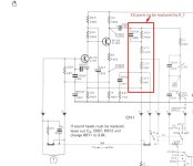
Here is the original schematic of the A77's FE (dc-supply is 19V)
to be honest, I never looked into 'noise matching', neither theoretical nor practical.
It is only recently that I am VERY curious to learn it for hobby purposes, hence down to full theoretical details and inclusive hands on. Can you recommend some good readings?
I understood your point with Z_in. This solves my confusion.
Also, noise matching is different from impedance matching.
But still not clear what next: how to marry the Z_source with Z_in and obtain best noise performance?
Is there a definition for it?
To your last questions regarding my choice, the answers today are disappointingly simple :
- wire can be modeled analytically and by simulations; another head cannot. The scope is to obtain an absolute calibration, not a relative one.
- wire can be precisely aligned to the gap. A microscope can have a direct view on both of them. Two heads cannot be aligned gap to gap equally good and easy. But your hint is considered, because maybe it will be 'easier' this way.
These days I realized that there might be many problems with wire too. Hopefully manageable. For example the skin depth effect might force to obtain good enough results only at higher frequencies. I hope that besides simulations, a few tricks can help to lower the frequency:
- use lithographic Au-wire which is then transferred between Kapton-PE foils 1um each: the other side of PE can be thermally bonded to the head. Then, is even better than wire alone: Au instead of W for smaller skin depth, and Kapton-PE interface to be able to run the magnetic tape onto it.
- use LN2 vapors to go to 77K (or even LHe for 4.2K): there the conductivity increases already 10x and skin depth decrease ca. 3x while the magnetic properties of head should stay rather constant (my assumption).
Based on my head-gap simulations and readings from winter holiday, so far I strongly prefer a wire solution.
But it does look that it will be a longer project (inclusive noise-matching reading), not an Easter one. Not easy to replicate NIST/MRL devices and results in short time and with far less resources.
The higher voltage replacements for BC550 seemed feasible a week ago.
Here is the original schematic of the A77's FE (dc-supply is 19V)
Attachments
15 years ago, I had a request to come as physics consultant for my HW colleagues for a front end. In my photodiode's proposal FE for 50-200KHz I used the LMP7721 opamp from TI with 3fA bias. Maybe now TI have more&better opamp offers. In TIA configuration the R_f=120-160dB it worked well for prototype, although in dead-bug construction and with a dedicated mini-box, but obtaining a gigantic + 30dB SNR performance vs their BJT-based old ones. Then some idiots wanted to put it in open case (not even some thin walls around), in the same PCB (low cost substrate and layout not optimized, not even guard traces) next to digital circuitry, ca. 1" apart from it. It failed, of course, and TIA being 'too complex' they switched back to the lousy performing BJT opamps. But at least they kept my proposals for new sensors 🙂TIAs often use a FET at the input because bias-current noise from the input transistor is often a very important performance limiter; the bias current from a bipolar transistor is source of shot noise and makes them less attractive. But voltage noise from the input transistor is also problematic, worsened by the shunt capacitance of the photodiode. A complex topic.
Of course the R804 (similar to open-loop gain) must be adjusted for maximum possible OL gain. I could set it stable for around 70dB.Here is the original schematic of the A77's FE (dc-supply is 19V)
With surprise, I measured the same setup a TIA on Rf 10^7 (140dB) setting: was barely able to match the Revox FE. The TIA had still ca. 5dB SNR less than the A77. I cannot understand how. I can only suspect that TIA was optimized for capacitive source... but 70dB vs 140dB and still not equal... hard to figure it out why.
Thanks,2SC2705
2SA1145
have a hint for their typical noise figure?
You need 5v to 20v on the BC550. The next stages provide more gain. Best a single transistor can do is 300x voltage gain with a fair bit of distortion.
The amp being the evaluated was the LMP7721? Its bias current is very low, so current noise doesn't seem a likely problem. I can only guess that voltage noise density might have been the culprit in your disappointing result. LMP7721 says Vn at 1 kHz is about 6.5nV/√Hz. I don't what Vn in the Revox might have been but might have been less. On the other hand, current noise was surely better in the TI than the Revox, but Vn may have dominated. Did you measure noise in a defined bandwidth with any difference in gain accounted for? Accurate noise measurement is very challenging and you need a low frequency spectrum analyzer or FFT to have good insight to performance issues.Of course the R804 (similar to open-loop gain) must be adjusted for maximum possible OL gain. I could set it stable for around 70dB.
With surprise, I measured the same setup a TIA on Rf 10^7 (140dB) setting: was barely able to match the Revox FE. The TIA had still ca. 5dB SNR less than the A77. I cannot understand how. I can only suspect that TIA was optimized for capacitive source... but 70dB vs 140dB and still not equal... hard to figure it out why.
I'm attaching a data sheet for BF862. Note 0.8 nV/√Hz at 100kHz. It was quite a remarkable part and a shame it was EOL. The CPH9310 isn't nearly as well characterized, but seemed to behave comparably in my application. But that was well above audio frequencies, so I'm projecting on faith that it performs well at audio.
Attachments
To obtain extremely low noise from a very low-resistance signal source, it is necessary to use transistors with a low base body resistance Rb. For example ZTX690B. And there is no need to force the gain.
Apologies: no.typical noise figure
But I did recall that transistors are paralleled to reduce noise, so bigger silicon may intrinsically be lower noise, so I would expect them to behave very well.
They are cheap too, if you want to try them 🙂
Maybe a silly idea, but you could use one head (one of those to be aligned) to record and one to play back. Record a high frequency signal with slow tape speed and adjust the added head for max output (simple azimuth technique).Two heads cannot be aligned gap to gap equally good and easy.
But of course that does not solve the model problem ...
Dyslexia no problem. I have it too.
a) The LMP7721 I used it years ago for a TIA with great results in a prototype for 50-200KHz photodiode FE.
b) Last weekend evaluation was a test for the A77's FE vs. the DHPCA-100 (a commercial item from Femto).
On the A77's FE side: the input noise was simulated and roughly measured at around 4nV/sqrHz (f > 1KHz).
On the commercial TIA side: I have no idea what the DHPCA-100 has in it. Maybe I should have used a DLPCA model.
If I have time&drive this weekend, I'll power up the NimBin crate for using the old ORTEC or Canberra preamps. I understood that both have custom made FETs (very large ones, their own Fab production, not commercial). This is 70's tech, supposedly believed to be much better than modern commercial ones (because of custom designed&made FET parts).
No, we're mixing things up here.The amp being the evaluated was the LMP7721? Its bias current is very low, so current noise doesn't seem a likely problem. I can only guess that voltage noise density might have been the culprit in your disappointing result. LMP7721 says Vn at 1 kHz is about 6.5nV/√Hz. I don't what Vn in the Revox might have been but might have been less. On the other hand, current noise was surely better in the TI than the Revox, but Vn may have dominated. Did you measure noise in a defined bandwidth with any difference in gain accounted for? Accurate noise measurement is very challenging and you need a low frequency spectrum analyzer or FFT to have good insight to performance issues.
a) The LMP7721 I used it years ago for a TIA with great results in a prototype for 50-200KHz photodiode FE.
b) Last weekend evaluation was a test for the A77's FE vs. the DHPCA-100 (a commercial item from Femto).
On the A77's FE side: the input noise was simulated and roughly measured at around 4nV/sqrHz (f > 1KHz).
On the commercial TIA side: I have no idea what the DHPCA-100 has in it. Maybe I should have used a DLPCA model.
If I have time&drive this weekend, I'll power up the NimBin crate for using the old ORTEC or Canberra preamps. I understood that both have custom made FETs (very large ones, their own Fab production, not commercial). This is 70's tech, supposedly believed to be much better than modern commercial ones (because of custom designed&made FET parts).
Indeed it is about the model problem. Yes, you are right that a relative calibration can be done 'easier' with another (play) head. Heck, it is even possible to use a simple coil (hence more turns and much more signal vs. 1 turn).Maybe a silly idea, but you could use one head (one of those to be aligned) to record and one to play back. Record a high frequency signal with slow tape speed and adjust the added head for max output (simple azimuth technique).
But of course that does not solve the model problem ...
If I use an erase head as pick-up: this has quite ideal L+R behaviour up to 50KHz at least. But the gap size is 50x bigger
In all these cases, remains the model unknown parameter set: how the flux will be routed, how much linkage it is, etc.
The easiest way: simply record copies of a new MRL tape on a very good machine (Ebay is full of such offers, still expensive). I still have my own reference tapes, like Agfa 19H, Grunding, MRL, etc. They are all not yet too bad.
But, I am set for an absolute flux calibration of the Rec/Play heads. So... I guess the appropriate R&D game must be played somehow 🙂
Two thoughts:
The single turn has such low impedance that current noise is probably of little concern, so focus on lowest noise voltage for preamp. I.e TIA not needed/best option?
What about exchanging roles? Transmit on single tun and receive on tape head?
The single turn has such low impedance that current noise is probably of little concern, so focus on lowest noise voltage for preamp. I.e TIA not needed/best option?
What about exchanging roles? Transmit on single tun and receive on tape head?
As long as you choose sensible values for the feedback impedances, the noise of a feedback amplifier will be dominated by the input stage, no matter whether it is a transimpedance, transconductance, voltage, current or double-loop amplifier.
Nonetheless, I think a transimpedance amplifier will be very inconvenient. Its loop gain will be almost directly proportional to the source impedance, including any cable between the source and the amplifier. If you want to keep it stable for different low-inductance pick-up coils and cable lengths, something with a voltage input should be easier.
Nonetheless, I think a transimpedance amplifier will be very inconvenient. Its loop gain will be almost directly proportional to the source impedance, including any cable between the source and the amplifier. If you want to keep it stable for different low-inductance pick-up coils and cable lengths, something with a voltage input should be easier.
- Home
- Amplifiers
- Solid State
- any audio BJT low noise but very high voltage?