Does anyone have a clever solution for adding a grid stopper resistor to an antique-style top grid cap input tube? It seems easy enough to solder a resistor between the wire and grid cap, but I'm curious to know if there is a way to do it that will not appear "rigged."
This is for restoration of a 1939 Epiphone Electar Zephyr. It has required lots of rerouting, especially the A/C Mains, in order to quiet it down. It's still picking up very faint RF, almost to the point where you can hear music from a radio station playing through.
The preamp tubes are 6C6.
This is for restoration of a 1939 Epiphone Electar Zephyr. It has required lots of rerouting, especially the A/C Mains, in order to quiet it down. It's still picking up very faint RF, almost to the point where you can hear music from a radio station playing through.
The preamp tubes are 6C6.
Try using shrink tubing, or better yet, spaghetti tubing over the resistor and wire.
They are available in black.
Cover over the resistor and the wire all the way through the chassis hole so the end of the tubing can not be seen.
Looks like insulated wire (which it will now be . . . double insulated).
Use a grommet on the hole in the chassis, the spaghetti should look good going through that.
You could just use a carbon comp resistor and it would look vintage.
Another possibility is using cloth insulation and covering both resistor and wire lead with it.
Another possibility is using cloth insulation and covering both resistor and wire lead with it.
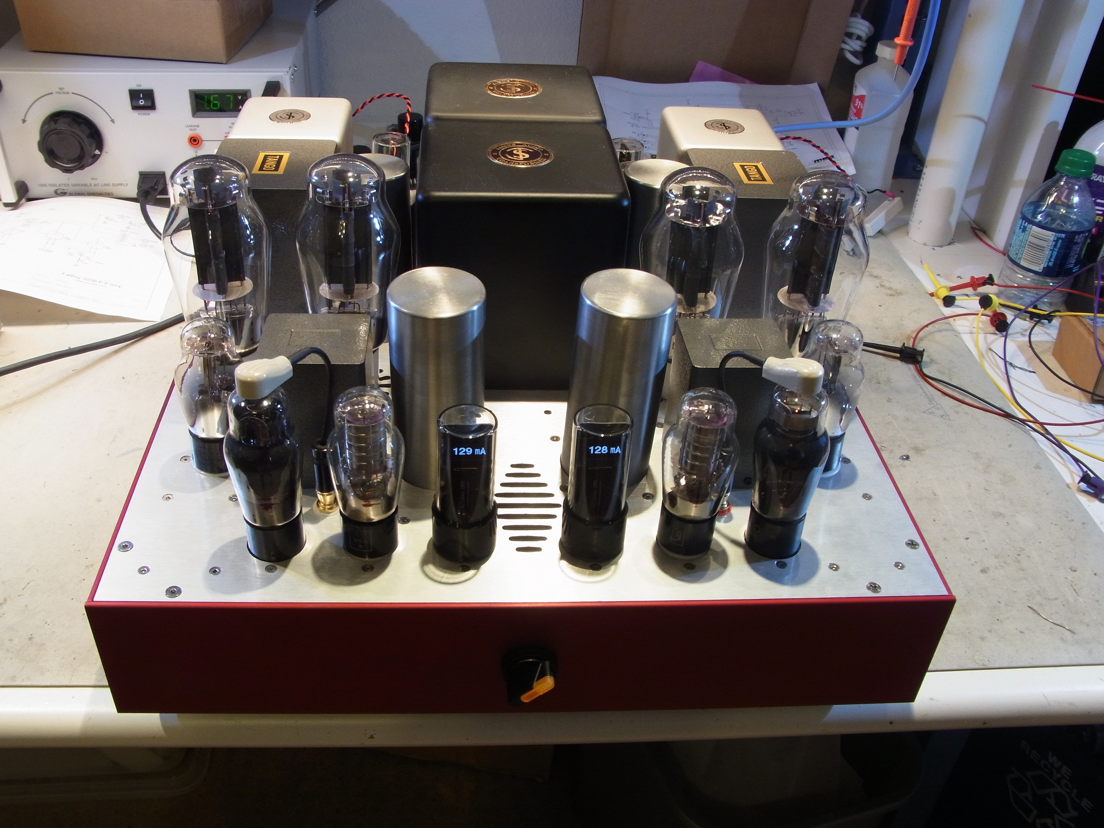
These tubes have low enough gm that you really don't need a grid stopper.
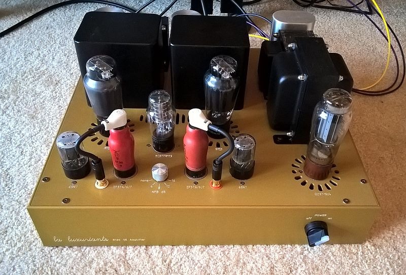
(These are EF36, pretty much the same as 6J7 or 6C6).
(This is 6C6).
Pete
(These are EF36, pretty much the same as 6J7 or 6C6).
(This is 6C6).
Pete
I would place a 120pF capacitor in series with a 10k resistor across their anode load resistors, R9 & R19, to tune out that very high frequency interference,