I couldn't find the artical on Broskie's site where that circuit is described.
What are the conditions for that to work? This implementation would need a double mono build with separate PSU for left and right channel, doesn't it? Otherwise the channels are connected through the single PSU return anyways.
So what is described here is two channels with their own power supplies that have these two channels connected to a common PE and chassis ground through their own lifting resistor???
Last edited:
In the end they will be connected together anyway because the signal share a common ground from the source.
The original circuit without the red crosses and without the jumpers seems OK.
It isolates the signal ground from the dirty mains ground but will limit the voltage between the two in case of a failure.
Jan
The original circuit without the red crosses and without the jumpers seems OK.
It isolates the signal ground from the dirty mains ground but will limit the voltage between the two in case of a failure.
Jan
That is just a link to a superfluous pcb. My question was about the circuit in my post (#21) that was originally posted in #2.
I was looking for the original post by Broskie that image appeared in as it doesn't make much sense as is.
I was looking for the original post by Broskie that image appeared in as it doesn't make much sense as is.
It's a very much used basic circuit.
The 'net is full of it, even here at diyaudio.com.
I can't find anything wrong with it; what do you think is wrong with it?
Jan
The 'net is full of it, even here at diyaudio.com.
I can't find anything wrong with it; what do you think is wrong with it?
Jan
It is not about the bridge + RC in itself but the use in the posted circuit. See post #21 and your response in #22.
It's a C, an R and a set of anti-parallel diodes all in parallel and between gnd and mains ground.
What's wrong with it? As I said, it's a standard circuit, everybody and their grandmother uses it.
I don't understand your question/issue, sorry.
Jan
What's wrong with it? As I said, it's a standard circuit, everybody and their grandmother uses it.
I don't understand your question/issue, sorry.
Jan
The bridge + RC is not the point. That is old news. It works, nobody argues that.
Look at that image which was said to be taken from Broskie's site:

My question is: what is the context in which it makes sense to use TWO bridge/rc units, one per channel? Maybe in a double mono build with separate power supplies per channel, otherwise L and R ground would be connected through PSU ground and one bridge/RC would be enough.
And as you said in #22 not even then as grounds are most likely connected in the source anyways.
Therefor I was asking for a link to the original article by Broskie to put that in context, as usually he doesn't post nonsense, unless to illustrate an issue.
Look at that image which was said to be taken from Broskie's site:
My question is: what is the context in which it makes sense to use TWO bridge/rc units, one per channel? Maybe in a double mono build with separate power supplies per channel, otherwise L and R ground would be connected through PSU ground and one bridge/RC would be enough.
And as you said in #22 not even then as grounds are most likely connected in the source anyways.
Therefor I was asking for a link to the original article by Broskie to put that in context, as usually he doesn't post nonsense, unless to illustrate an issue.
Ground loops often occur between channels with many common amplifier layouts, and this will break those. It’s better not to have them in the first place, but this is one way of band aiding it.
Rectifiers in the safety ground path is not considered 100% safe because the CAN fail open if the internal bond wires fuse or the semiconductor die physically cracks. Not that likely with a big 35 amp block with fast-on lugs, but it CAN happen and you’ll never see this pass safety certs for that reason. In the practical sense it’s been fine on most of my old unbalanced PA equipment and faults through the rectifier do open the mains fuse, but anything I use now simply goes to balanced interconnect. Do NOT use a little 4 or 10 amp SIP pack for this! They simply are not as reliable. You only NEED a 50 volt version here, since it will never see more than two volts. Those can be had on the surplus market much cheaper than the 600 volt ones you would actually use the the power supply. If you find 50 amp versions, use those. I’ve used those to turn over starter motors without them dying instantly.
Rectifiers in the safety ground path is not considered 100% safe because the CAN fail open if the internal bond wires fuse or the semiconductor die physically cracks. Not that likely with a big 35 amp block with fast-on lugs, but it CAN happen and you’ll never see this pass safety certs for that reason. In the practical sense it’s been fine on most of my old unbalanced PA equipment and faults through the rectifier do open the mains fuse, but anything I use now simply goes to balanced interconnect. Do NOT use a little 4 or 10 amp SIP pack for this! They simply are not as reliable. You only NEED a 50 volt version here, since it will never see more than two volts. Those can be had on the surplus market much cheaper than the 600 volt ones you would actually use the the power supply. If you find 50 amp versions, use those. I’ve used those to turn over starter motors without them dying instantly.
Even with one power supply it can happen. Hook up one RCA cable and it’s fine. As soon as you plug in the other channel, hummmmmmm. You want to really minimize problems? Co-locate the input/feedback grounds for both channels. But that doesn’t make a pretty, aesthetically pleasing, easy to build/service layout…..
Even with one power supply it can happen. Hook up one RCA cable and it’s fine. As soon as you plug in the other channel, hummmmmmm. You want to really minimize problems? Co-locate the input/feedback grounds for both channels. But that doesn’t make a pretty, aesthetically pleasing, easy to build/service layout…..
This wasn't in reply to you. Jan was replying to #29. At least I believe he did.
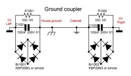
Where did you find this? You said it was from Broskie. Do you have a link where he posted that?You are right! A stronger bridge is required. Here is how I use the ground coupler. I assume the cabinet is always connected to the house's ground.
No, the idea is from the PS21 manual. Perhaps you can find it online, I don't know. Mine obviously, is for a dual mono same cabinet equipment. My first draw was missing the connection points.
The schematic shows isolated left and right channel reference, suggesting a full dual-mono amplifier construction. I use such dual GND lifter too in my own dual-mono amps, except the rectifier bridges being 50A rating plus different wiring as shown in post #13 to double up the fault current capacity. By the way, I would never use a 2A rectifier bridge for PE lifting.My question is: what is the context in which it makes sense to use TWO bridge/rc units,
The diode drops also prevent a ground loop current from flowing between two devices if there is a slightly different residual voltage on their ground connections; as an example, if the 2 devices are plugged into different outlets, and there are different small residual voltages on the two outlets' ground connections. This could cause a small but hum-inducing circulating current to flow. The diodes still provide a safety ground, even if there is a diode drop present, since 0.7 or so Vac won't hurt anyone who comes into contact with it. This sort of a circuit can work in any setting, such as a tube amp. The big thing is that if there is a power line fault condition in the equipment, the diodes must be able to conduct enough current to blow the fuse or breaker in the equipment. If they blow open, then a serious shock hazard would be present.I came across this picture while searching grounding articles. Supposedly the anti parallel diodes and x2 capacitor protect from EMI while still providing ground protection.
Any thoughts on incorporating this on a tube amp?View attachment 1125949

Ok, thanks. That clears that up.No, the idea is from the PS21 manual. Perhaps you can find it online, I don't know. Mine obviously, is for a dual mono same cabinet equipment. My first draw was missing the connection points.
- Home
- Amplifiers
- Tubes / Valves
- Anti parallel diode at ground