...
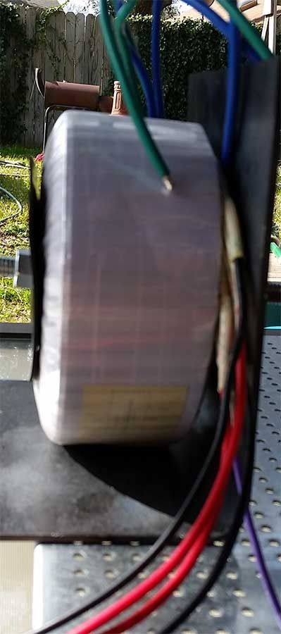
I have a couple of examples and not sure if either is the correct method of mounting when the transformer is mechanically isolated from the chassis.
In this situation should a wire from the center bolt be brought to either star ground, or to a connection point on the chassis directly under the toroid?
Asking first from safety perspective, second from keeping interference to a minimum.
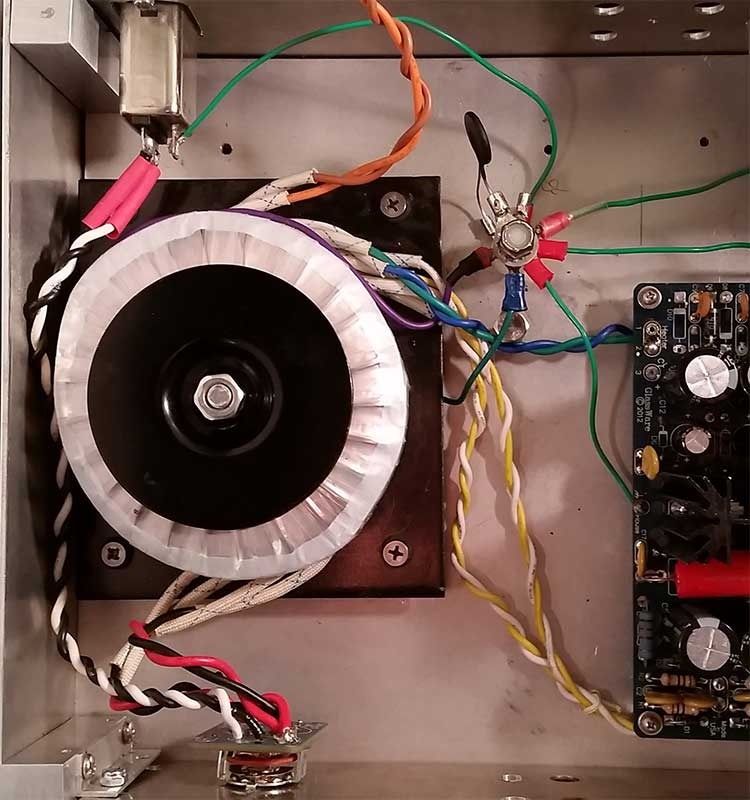
Here is the first example on a pre-amp. The steel plate is mechanically isolated from the chassis. The star ground point is a nylon bolt. The bottom of the nylon bolt has a metal nut holding the safety ground against the chassis. Above that is a nylon spacer, then the rest of the grounds brought to one point. The questionable unnecessary wire is the one in the 6 o'clock position which runs from the bottom of the bolt on the steel plate.
Between the safety ground and the rest of the star ground is a current inrush limiter, STM CL-60. I don't know if it is the best thing to use but after adding this, and moving the star ground off direct contact with the chassis it is a lot quieter but not perfect.
The signal ground is not attached to the chassis, only to isolated RCA input and output. I have removed the attenuator, source selector, coupling capacitor selector ... everything except the power switch.
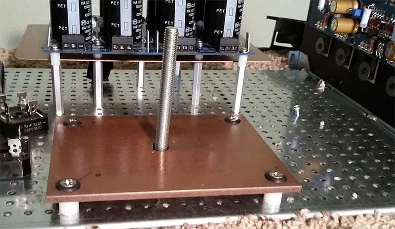
Here is another application. This time I put it on a steel plate and raised it off the bottom of the chassis is so I can keep the AC lines running along the bottom. The DC and signal would be further away and in some situations shielded to hopefully reduce interference. The power supply has a thin steel sheet under it. Both pieces I attempted a copper deposit on as a novelty. It didn't end up looking very good so spray painted a copper tone paint over the thin layer of copper.
I haven't finished because it is more cramped than planned.
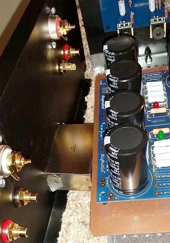
The IEC input is fused and shielded, it is mounted center and low on the back panel which would go under the power supply.
A view from the top.
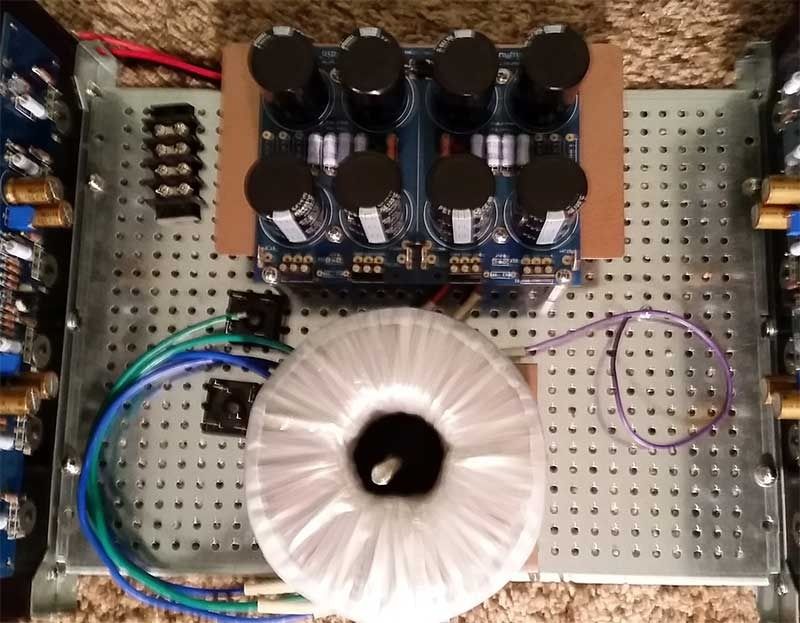
An option I am considering because of the space issue.
All of my search results over the last week have come up with a general consensus to bolt the transformer directly to the chassis, these are just some things I have been playing around with. Maybe they are bad, maybe good. Trying to finish up so I can use these space heaters before winter is over!
I have a couple of examples and not sure if either is the correct method of mounting when the transformer is mechanically isolated from the chassis.
In this situation should a wire from the center bolt be brought to either star ground, or to a connection point on the chassis directly under the toroid?
Asking first from safety perspective, second from keeping interference to a minimum.
Here is the first example on a pre-amp. The steel plate is mechanically isolated from the chassis. The star ground point is a nylon bolt. The bottom of the nylon bolt has a metal nut holding the safety ground against the chassis. Above that is a nylon spacer, then the rest of the grounds brought to one point. The questionable unnecessary wire is the one in the 6 o'clock position which runs from the bottom of the bolt on the steel plate.
Between the safety ground and the rest of the star ground is a current inrush limiter, STM CL-60. I don't know if it is the best thing to use but after adding this, and moving the star ground off direct contact with the chassis it is a lot quieter but not perfect.
The signal ground is not attached to the chassis, only to isolated RCA input and output. I have removed the attenuator, source selector, coupling capacitor selector ... everything except the power switch.

Here is another application. This time I put it on a steel plate and raised it off the bottom of the chassis is so I can keep the AC lines running along the bottom. The DC and signal would be further away and in some situations shielded to hopefully reduce interference. The power supply has a thin steel sheet under it. Both pieces I attempted a copper deposit on as a novelty. It didn't end up looking very good so spray painted a copper tone paint over the thin layer of copper.
I haven't finished because it is more cramped than planned.

The IEC input is fused and shielded, it is mounted center and low on the back panel which would go under the power supply.

A view from the top.

An option I am considering because of the space issue.

All of my search results over the last week have come up with a general consensus to bolt the transformer directly to the chassis, these are just some things I have been playing around with. Maybe they are bad, maybe good. Trying to finish up so I can use these space heaters before winter is over!
Last edited:
Bolt the PE wire direct to Chassis at a dedicated permanent location near the incoming mains cable/socket.
Use a connection and wire that can survive the kA of Fault Current that can flow in the event of a catastophic mains failure inside the enclosure.
Create a separate connection from the Main Audio Ground (MAG) to Chassis and locate that chassis connection next to the MAG.
This connection also needs to survive the kA of Fault Current.
It is my view that the MAG should be located NEAR all of the following:
The speaker output terminals, the input signal sockets, the amplifier. This nearness requirement in part determines the layout inside the chassis. The amplifier and the two sets of sockets should be near each other and the MAG located at their centroid.
There is no need to bolt the toroid transformer direct to the chassis/enclosure.
There is a need to ensure the transformer cannot break free from it's mounting and damage the primary wiring such that a short to chassis could occur if the amplifier were accidentally dropped.
Finally, all exposed conductive parts should be connected to the protected enclosure.
Last edited:
- Status
- Not open for further replies.