I have read on several occasions about using inductive RIAA filters, and how some pundits think they sound better than RC filters. One opmap-based feedback design that looked reasonably easy to implement was published in Audio Express a few years ago.
Attached is a schematic for a gain cell using 2 JFETs and feedback-style inductive equalization. The equalization is set up fro the first 50Hz corner.One could increase the gain of the circuit and add the second corner, or put the higher frequency corner in a second stage. The gain cell uses capacitive coupling, but nothing's perfect, and the couopling capacitor value is small enough that one could contemplate using a teflon capacitor.
Anyway, food for thought. I won't be building this one for a while, as I have a big backlog of projects, but I thought I'd sling the concept out and let i fester in public...
Attachments
Attached is a picture of a more complete circuit, though I think a follower might be advisable for interfacing to the cold, cruel world. I want to look a the turnover points a bit more closely, though the 1kHz gain as plotted by PSpice is pretty close to my goal of 40 dB.
Attachments
R15 should be 1.18k to roll off the gain reduction of the second stage at 50 kHz. Ill try rolling that value into the sim at work tomorrow.
Hi,
some cool stuff you have here ;-)
Still, your inductors are huge! I mean 159mH will be the big block of inductors; that beast will in practice maybe pickup so much noise that it's no longer useable for a phonostage. Further, the inductor is then iron-cored which usually limits bandwidth (probably small problem) and introduces distortion.
Have fun, Hannes
The inductor values are actually rather small compared to many other inductive RIAA setups. Wound on gapped ferrite pot cores, the inductors will also be reasonably sized and linear. The 159 mH inductor is ~500t on a 2616 pot core gapped for 630 nHT^2 inductance coefficient (a standard size and inductance coefficient from many suppliers). A 3019 core may be a better choice, requiring fewer turns. Pot cores are to a large extent self-shielding, and cans are offered as accessories that offer even more shielding. After all, pot cores were developed for use in high precision filter circuits where stability, precision, and freedom from noise pickup are all very important. I'm more worried about stray capacitance, though that can be fixed to a certain exent with a multisection bobbin (also a standard offering). The main thing to worry about is factoring the wire resistance into the RIAA filter settings.
I deliberately forced the design to accomodate a small value of gain setting resistor in order to make the inductor values more reasonable. A standard passive RIAA network would need to be low impedance (the standard ones available are 600 ohms and cost hundreds of dollars). At 600 ohms, the inductors are huge, and it requires a matching transformer or other sleight of hand to drive them. This approach here is very similar to one mentioned in a 2003 article in Audio Xpress, but that guy used an opamp, and I have a fetish for discrete JFET designs...
I deliberately forced the design to accomodate a small value of gain setting resistor in order to make the inductor values more reasonable. A standard passive RIAA network would need to be low impedance (the standard ones available are 600 ohms and cost hundreds of dollars). At 600 ohms, the inductors are huge, and it requires a matching transformer or other sleight of hand to drive them. This approach here is very similar to one mentioned in a 2003 article in Audio Xpress, but that guy used an opamp, and I have a fetish for discrete JFET designs...
you can find some info here http://www.intactaudio.com/forum/vi...start=60&sid=6dea84b504bac5e3b0078d68807f414b
there is Thread on 1k5 too ,with single coil , not like S&B ,Tango or SilK that are complete module
tango/pultec on pic
there is Thread on 1k5 too ,with single coil , not like S&B ,Tango or SilK that are complete module
tango/pultec on pic
Attachments
The local surplus emporium has canned 4229-sized inductors - as a bonus, they have the PC-mount base plates, and weren't varnished, so they're easy to take apart. As a last cherry on top, the bobbins are 2-sectioned, for a lower winding capacitance. These cores are a little larger than I envisioned, but they have everything needed to make at least the low frequency inductor for a L/R-type RIAA filter. Once I get my BA 2009 project out of the way, this might be next up.
for what I read for good riaa ,under 0,3db we must use lower RLc , the S&B give up on 10k.....too bad
That's why I'm using the circuit configuration I chose - it allows me to use 50 ohm impedance networks. This is much more managable and may be workable without all the extra components to compensate for strays. Time will tell. Fortunately, we have a very good impedance analyzer at work, so I'll be able to really scope out the inductors once they're wound.
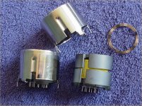
Just so folks know what to look for, attached is a picture of some ferrite pot cores, one all canned up with shield and PC mount bottom plate, another disassembled so you can see the slightly separated core halves, the bobbin inside them, the bottom plate, the can, and the wavy washer placed inside the can on top of the core so that the ferrite pieces don't get crunched when the can is clinched tight to the bottom plate. These cores happen to be 42 X 29 mm,pretty much the largest size commonly available. There's a host of smaller sizes, for this application those from 26 X 16 mm upward are probably most suitable.
Attachments
That's all very fine, but the entire thrust of this thread is to get away from using those networks. There are several other threads dealing specifically with what you're trying to do. A search will find them.
FWIW, inductors are the most impure electronic component. If you spend any serious time measuring them you'll find that only an air core is linear and can achieve really low THD levels, at the expense of size and internal resistance of course. Mounting is always an issue, as even mounting near a copper ground plane changes the characteristics. I've no doubt that the parasitics can be taken care of in the design, but unless one is trying to build a steep and exotic multi-order filter, using inductors seems like more of a novelty than anything else. And this from somebody who actually likes winding and using inductors!
This is why I'm aiming for low impedance network, again, to reduce the necessary inductance as much as possible. Pot cores with a reasonable air gap are pretty linear, especially as they are seeing low current and low signal levels. The pot core geometry is to a large extent self-shielding - adding the cans as shown in the previous picture kills electrostatic noise coupling. Pot cores were used extensively in the telecommunications industry for precision filters, for good reason. At any rate, I'm trying the inductive filters out of curiosity, and choosing the simplest way to do it that I can think of. I, too, work extensively with inductors, but mostly in the grubby power supply realm - a different matter altogether.
wrenchone sorry if you thinks that I disturb your work ,I no need info, I try add as I study for a month in all world wide web
if we can trust Bench-Thortsten-Mayer and a lot skilled diy ,this coil works a lot better then RC riaa at last on tube,as they put under x-ray with real misure....only problem is$$$
best
if we can trust Bench-Thortsten-Mayer and a lot skilled diy ,this coil works a lot better then RC riaa at last on tube,as they put under x-ray with real misure....only problem is$$$
best
- Status
- Not open for further replies.
- Home
- Source & Line
- Analog Line Level
- Another Wrench In the Works... Inductive RIAA