Hi all,
I received from a friend a pair of audio monitors “nEar 08 Classic”.
One is not working.
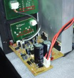
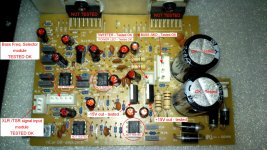
I opened it and noticed that the PCB was not in good shape.
It seems that "ESI" is not supporting this model any longer.
I found that this audio monitor circuitry uses an internal active crossover that divides the signal @2700Hz and then sends each channel ( Mid/Woofer + Tweeter ) to it’s own TDA7294 AMP that delivers 75W @ 4 Ohm for each speaker (the speakers are 4 Ohm each, well, in fact the Tweeter are 3.5 Ohm to be precisely exact).
See attached photos for clarification of the stated above.
I tested the one that is working and I noticed that this circuitry is a bit noise (high-hiss), at stand-by, so I decided to replace most of the circuit design by a new option.
I’m going to keep and use the power supply symmetric transformer (rated 22V-0-22V @1.8A).
I’m also planning to maintain the “Balanced Line in TSR /XLR" with the passive volume “pot” unit.
All the rest of the circuit goes by-by.
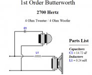
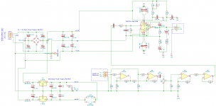
The main idea is to assemble a new circuit that receives the Line IN balanced audio signal, process it to standard (+/-) audio signal and then sends it to a single TDA7294 AMP that should deliver 60W @ 4 Ohm ( 20HZ to 20Khz ) from there the signal flows to a simple “1st Order Butterworth” passive crossover (see image) and then to the ( Mid/Woofer + Tweeter ).
I added my circuit schematic concept (in attach) for the ones that love to discover problems and faults in the circuit designs.
Enjoy and let me know if you think this is going to work, or if I’ll end up exploding my house.
Many thanks.
Ben.
I received from a friend a pair of audio monitors “nEar 08 Classic”.
One is not working.
I opened it and noticed that the PCB was not in good shape.
It seems that "ESI" is not supporting this model any longer.
I found that this audio monitor circuitry uses an internal active crossover that divides the signal @2700Hz and then sends each channel ( Mid/Woofer + Tweeter ) to it’s own TDA7294 AMP that delivers 75W @ 4 Ohm for each speaker (the speakers are 4 Ohm each, well, in fact the Tweeter are 3.5 Ohm to be precisely exact).
See attached photos for clarification of the stated above.
I tested the one that is working and I noticed that this circuitry is a bit noise (high-hiss), at stand-by, so I decided to replace most of the circuit design by a new option.
I’m going to keep and use the power supply symmetric transformer (rated 22V-0-22V @1.8A).
I’m also planning to maintain the “Balanced Line in TSR /XLR" with the passive volume “pot” unit.
All the rest of the circuit goes by-by.
The main idea is to assemble a new circuit that receives the Line IN balanced audio signal, process it to standard (+/-) audio signal and then sends it to a single TDA7294 AMP that should deliver 60W @ 4 Ohm ( 20HZ to 20Khz ) from there the signal flows to a simple “1st Order Butterworth” passive crossover (see image) and then to the ( Mid/Woofer + Tweeter ).
I added my circuit schematic concept (in attach) for the ones that love to discover problems and faults in the circuit designs.
Enjoy and let me know if you think this is going to work, or if I’ll end up exploding my house.
Many thanks.
Ben.
Attachments
Last edited:
Why do you call 1st order filters 'Butterworth'?
And, although it is a SS related question, you'd probably get more answers if you'd put it in the Chip Amps branch.
Best regards!
And, although it is a SS related question, you'd probably get more answers if you'd put it in the Chip Amps branch.
Best regards!
Last edited:
The complexity or filter type is defined by the filters “order” and is dependant upon the number of reactive components such as capacitors or inductors within its design.Why do you call 1st order filters 'Butterworth'?!
This simple crossover is rated "a first-order filter" bcause it has a standard roll-off rate of 20dB/decade or 6dB/octave.
I'm not sure if I replied to your question.
Noted. Many thanks for the advice. 🙂... you'd probably get more answers if you'd put it in the Chip Amps branch.
Best regards!
A 1st order HP or LP is just a 1st order filter, nothing else. There ain't no characterictics such as Butterworth, Chebyshev, Bessel etc.
Best regards!
Best regards!
There ain't no characterictics such as Butterworth, Chebyshev, Bessel etc.
Best regards!
I respect your point of view.
I am not even picky about "definitions".
The important thing to me is not how things are classified or "called".
What matters to me are results.
Yet, I understand the "need" for conventions (so one and the other knows exactly what they are referring to).
Anyway, taking your statement, I guess many people are wrong about crossover filters:
"The Butterworth filter is a type of signal processing filter designed to have a frequency response as flat as possible in the passband."
Butterworth filter - Wikipedia
A 1st order HP or LP is just a 1st order filter, nothing else. There ain't no characterictics such as Butterworth, Chebyshev, Bessel etc.
Best regards!
Alas we are talking crossovers, and you are wrong. Thats the circuit of a 1st order Butterworth crossover. The "Butterworth" bit tells you how much overlap there is between high pass and low pass sections (ie +3dB peak).
Butterworth analyzed many-many filters.
The first-order is in his list, but of course rather trivial.
To get back ON TRACK.... Converting a bi-amplified system to a passive crossover will work, obviously, but trades-off several dB of headroom and may need a Power trimmer to balance the two drivers. Also a 1st-order crossover allows quite a lot of midrange into the tweeter, which may not be selected to handle heavy below-band signal.
To get back ON TRACK.... a 1st-order crossover allows quite a lot of midrange into the tweeter, which may not be selected to handle heavy below-band signal.
Humm, you have a point here.
I know that the active crossover splits @2700Hz, maybe I can minimize/ compensate this issue by lowering the split frequency to @3000Hz?
Well, I have to test the crossover after assemble the rest of the circuit.
I'm a bit worried about the circuit regarding the signal input (based on the 4558D) and the final stage of the TDA.
I would like to hear some opinions of people that already assembled an amp with the TDA7294.
It is the first time I'm dealing with this chip.
Despite I've used the STMicroelectronics circuit reference, (and some other projects I found on-line to assemble the amp circuit) I'm not so sure if this circuit is the best approach to this chip.
A little help with this circuit would be much appreciated.
Thanks
Cheers.
Last edited:
Untrue. Any filter that fulfils the requirements of Butterworth (maximally flat frequency response) or Bessel (maximally flat group delay) criterion may be correctly called as such. Even though when it is trivial in the case of a first order filter.A 1st order HP or LP is just a 1st order filter, nothing else. There ain't no characterictics such as Butterworth, Chebyshev, Bessel etc.
Best regards!
Because there are questions arround the "nEar08 classic"Why do you call 1st order filters 'Butterworth'?
And, although it is a SS related question, you'd probably get more answers if you'd put it in the Chip Amps branch.
Best regards!
(8" Studio Reference Monitor) from German's brand ESI Audiotechnik - go to
ESI - Product Archive: nEar08 classic
and
ESI - Impressum
I would it filed under "Multi-Way".
As I know, you will get service manuals from this brand - ask there:
ESI - Legal Information
Because there are questions arround the "nEar08 classic"
(8" Studio Reference Monitor) from German's brand ESI Audiotechnik - go to
ESI - Product Archive: nEar08 classic
and
ESI - Impressum
I would it filed under "Multi-Way".
As I know, you will get service manuals from this brand - ask there:
ESI - Legal Information
Oh yes. I appreciate your tip.
Unfortunately your suggestion was the 1st thing I've tried.
ESI was very nice replying to me but they said that this model was exclusively sold by Thomann, so all requests related to this model should be addressed to Thomann instead of ESI.
Since this pair of Studio Monitors was bought long ago and Thomann no longer sell them, (they sell the new model "ESI uniK 08 Plus" instead), and because I also don't like the noise these audio monitors do in stand-by mode, I prefer to make a new circuit that may deliver "better audio" with less "stand-by noise" ratio.
I 'm not sure if I'll be able to achieve it, but I will surly try it. ;-)
the same issue was described in German there:
ESI nEar08 leichtes Rauschen normal? | Musiker-Board
Now I understand it exactly. To minimize noise in audio systems, one of the most important question is where must the attenuator (potentiometer for volume control) be arranged.
In general in front of the power amp input.
All other places will result in bad results for S/N ratio, because then the noise of the previous stages will not be attenuated in the low level areas.
This issue I have observed on a wide range of active loudspeakers, where the electronics was integrated in the speaker envelope.
An additional drawback is the fact, that the power amplifier modul is on the box resp. cabinet (microphonic effects).
Best solution is outsource of the complete electronics and using a potentiometer in front of the actually power amps - go to
1pcs original Japan ALPS motor Volume potentiometer 100K*6 channel | eBay
This I have done several times and the wanted success was present (i. e. unaudible noise in the low level area).
Last edited:
the same issue was described in German there:
ESI nEar08 leichtes Rauschen normal? | Musiker-Board...
...
Best solution is outsource of the complete electronics and using a potentiometer in front of the actually power amps - go to
1pcs original Japan ALPS motor Volume potentiometer 100K*6 channel | eBay
This I have done several times and the wanted success was present (i. e. unaudible noise in the low level area).
I noticed that in the nEar 08, the volume potentiometer is placed in the same PCB of the signal IN (where the TSR / XLR jacks are connected from an external audio source).
I'm planning to change it to the circuit of the 4558D signal processing chain (before the TDA amp).
Its possible to check this on the circuit image I posted, labeled as RV1. 🙂
So, I'm following your advice and moving the volume potentiometer from its original location to the final signal processing stage, right before the AMP.
Last edited:
A 1st order HP or LP is just a 1st order filter, nothing else. There ain't no characterictics such as Butterworth, Chebyshev, Bessel etc.
Best regards!
The characteristics around the break point frequency have a different gain curve for different models.
YouTube
- Status
- Not open for further replies.
- Home
- Amplifiers
- Chip Amps
- Another TDA7294 AMP replacement