Hi, I think it would be good to leave some more headroom for the source followers. With headroom I mean a bit more than the +20V (maybe +100V) and possibly more negative voltage as well (more than -100V, and larger resistor). The reason is that the capacitances of mosfets are not very linear when VDS becomes small, so it is better to have at least 30V VDS under all circumstances.
I think your definitive amplifier will have independent voltage sources (pots) for bias adjustments, to compensate for differences between GU50's?
have you looked into the 'bestpentode' connection for the input stage? I do not know if it works together with the local feedback arrangement, but I think it will. It could give a bit more gain, less noise, and possibly better balance in the LTP.
Good luck! 🙂
Please come back when you get some results, and I will share my Pyramid experiences. And probably PCBs. 🙂
Please come back when you get some results, and I will share my Pyramid experiences. And probably PCBs. 🙂
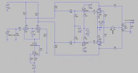
IRFP240 as followers at 90 mA? Surely not - there are far better suited MOSFETs, IRFP240 has WAY too much capacitance, and this will be extremely nonlinear as Vgd approaches 8-10V. Even at 100mA per follower (which seems a bit excessive but I am guessing you are trying to make the change in current lower as the G1 of the GU50 goes positive) there are better (smaller) MOSFETs to use, also a bit more voltage on the current 20V supply...
Last edited:
IRFP240 as followers at a few mA? Surely not - there are far better suited MOSFETs, IRFP240 has WAY too much capacitance.
Yes I know that. This is testing schematic in LTSpice. I am still looking for better MOSFET. Which one do you prefer?
Hi, I think it would be good to leave some more headroom for the source followers. With headroom I mean a bit more than the +20V (maybe +100V) and possibly more negative voltage as well (more than -100V, and larger resistor). The reason is that the capacitances of mosfets are not very linear when VDS becomes small, so it is better to have at least 30V VDS under all circumstances.
I think your definitive amplifier will have independent voltage sources (pots) for bias adjustments, to compensate for differences between GU50's?
have you looked into the 'bestpentode' connection for the input stage? I do not know if it works together with the local feedback arrangement, but I think it will. It could give a bit more gain, less noise, and possibly better balance in the LTP.
Very good idea for bestpentode, I must find the Linear Audio publicitation where is that described. I belive that is in volume 1?
I think your design lacks the possibility of adjusting the GU50's bias, doesn't it?
Best regards!
Best regards!
I think your design lacks the possibility of adjusting the GU50's bias, doesn't it?
Best regards!
As I wrote before - this is working schematic for LTSpice. I always do bias like this:
Attachments
As I wrote before - this is working schematic for LTSpice. I always do bias like this:
Hi,
it will be more comfortable to use two potmeters , one for the bias balance and another to set the idle current, like this example:
73
Wolfgang
Attachments

bias circuit
Hi,
I prefer this circuit:
http://www.diyaudio.com/forums/atta...1298561958-jj-kt88s-other-octals-kt88_amp.png
No matter which trimpot fails the bias voltage will go full negative and
switch-off the tubes.
No, I am not kruesi...but i use the same bias circuit for my amps.
regards
Hi,
I prefer this circuit:
http://www.diyaudio.com/forums/atta...1298561958-jj-kt88s-other-octals-kt88_amp.png
No matter which trimpot fails the bias voltage will go full negative and
switch-off the tubes.
No, I am not kruesi...but i use the same bias circuit for my amps.
regards
Hi,
I prefer this circuit:
http://www.diyaudio.com/forums/atta...1298561958-jj-kt88s-other-octals-kt88_amp.png
No matter which trimpot fails the bias voltage will go full negative and
switch-off the tubes.
No, I am not kruesi...but i use the same bias circuit for my amps.
regards
This is very smart circuit. Thanks for sharing.
This is very smart circuit. Thanks for sharing.
No problem.
Unfortunately not my invention...
When i thought i had a bright idea someone else already invented it...
regards
Frank
Hi,
Wow, nice approach!
73
Wolfgang
http://www.diyaudio.com/forums/attac...s-kt88_amp.png
No matter which trimpot fails the bias voltage will go full negative and
switch-off the tubes.
No, I am not kruesi...but i use the same bias circuit for my amps.
Wow, nice approach!
73
Wolfgang
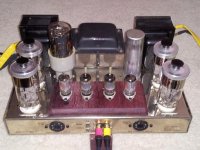
Dynaco GU50
40W GU50PP on Dynaco ST70 chassis (which retain only the transformers). Frequency response at 30W -3db @ 10 Hz, 55Khz.
The input & drivers tubes are 5814. It sounded so much better than my stock ST70 EL34. Just a quick fun experiment with Russian GU50 tube.
40W GU50PP on Dynaco ST70 chassis (which retain only the transformers). Frequency response at 30W -3db @ 10 Hz, 55Khz.
The input & drivers tubes are 5814. It sounded so much better than my stock ST70 EL34. Just a quick fun experiment with Russian GU50 tube.
Attachments
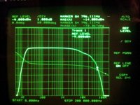
The frequency response at high end is not OK. It begins to drop above 2 kHz.
With original output transformers the response should be flat up to 50 kHz.
Have you optimized the GNFB loop ?
With original output transformers the response should be flat up to 50 kHz.
Have you optimized the GNFB loop ?
GU50 PP Dynaco
That's because I tested at 30W, close to full power, where it would tell me how the amp will perform with real music, I always test the amplifier at power level when clipping start. Most manufacturer specified frequency response at 1W , sure it looked much better on paper, but it wont tell you how it will perform when the music is demanding. Also, I used much less negative feedback then the original dynaco, -3db at above 40Khz is fine with me.
Below is frequency response with 1Watt into 8 ohm.
The frequency response at high end is not OK. It begins to drop above 2 kHz.
With original output transformers the response should be flat up to 50 kHz.
Have you optimized the GNFB loop ?
Last edited:
There is something wrong. Again, have you checked that the feedback loop is OK ?
Especially the capacitor (390 pF at the original schematic) from UL tap to cathode of 7199.
ST70 should give the same frequency response with 30 W and 1 W, like all well designed and built amplifiers.
Especially the capacitor (390 pF at the original schematic) from UL tap to cathode of 7199.
ST70 should give the same frequency response with 30 W and 1 W, like all well designed and built amplifiers.
- Status
- Not open for further replies.
- Home
- Amplifiers
- Tubes / Valves
- Another PP GU50