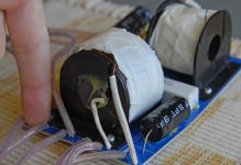
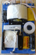
I'm trying to learn this stuff, slowly but surely 🙂 For now, could somebody please step me through this schematic. The literature for the speaker (Wharfedale Evo 30) says crossover points are 60hz and 3200hz, how is that possible with such small inductors? And also, I have the physical crossover out of the speaker and it has one pretty big iron core inductor that sure looks bigger than anything on this schematic! I can post a pic of it if it helps.
Attachments
Maybe the speaker plays down to 60hz. From what I see for components I do not see anything that indicates a 60hz crossover point.
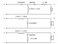
~1600hz if a 6 ohm low pass with what looks like a zobel is the lowest part. the center is a 12db/oct low pass and the top is a 18db/oct high pass with attenuation for the tweeter. If you have the nominal impedence of the drivers it would be easier to understand the crossover.
~1600hz if a 6 ohm low pass with what looks like a zobel is the lowest part. the center is a 12db/oct low pass and the top is a 18db/oct high pass with attenuation for the tweeter. If you have the nominal impedence of the drivers it would be easier to understand the crossover.
You probably could have guessed, but from top to bottom is the tweeter, midrange, then woofer. And like I was saying, the paperwork says the crossover points are 60hz for the woofer, bandpass 3200 for the mid, and 3200 highpass for the tweet.
Unless the woofer is somehow installed in a bandpass (mechanical) configuration through cabinet design there is no way those values could yield a 60Hz cut-off. Large ferrite-cored inductors could mean there's a mistake on the schematics printout.

LOL, just had a glance at the Wharfedale Evo. Should've done that first then I wouldn't have bothered with wild theories. Like Sreten posted it's a 2.5 way speaker, not a 3-way, and the LF cutoff is listed as 160Hz even though the literature is void of details on how this is achieved. Woofers are only 6-inchers (17cm) so my guess is that cabinet cavity bandpass filtering is used.
This being said the xover schematics still looks a bit odd, and it's out of phase.
This being said the xover schematics still looks a bit odd, and it's out of phase.
And more questions, sorry 🙂
Are the 20uf caps 50V pieces simply to cut costs? Is there any reason I couldn't upgraded them with a 20uf 250V cap? And what about adding small high-quality caps in-line with the big caps as a bypass ... is that generally a good idea?
Are the 20uf caps 50V pieces simply to cut costs? Is there any reason I couldn't upgraded them with a 20uf 250V cap? And what about adding small high-quality caps in-line with the big caps as a bypass ... is that generally a good idea?
TurboFC3S said:And more questions, sorry 🙂
Are the 20uf caps 50V pieces simply to cut costs? Is there any reason I couldn't upgraded them with a 20uf 250V cap? And what about adding small high-quality caps in-line with the big caps as a bypass ... is that generally a good idea?
Often better quality caps are used to bypass in parrallel not in series. 50V at 6ohms =416.7 W peak or about 296Wrms. You can try higher rated caps if you want but I would look at trying better quality ones instead of higher voltages alone.
ocool_15 said:Often better quality caps are used to bypass in parrallel not in series. 50V at 6ohms =416.7 W peak or about 296Wrms. You can try higher rated caps if you want but I would look at trying better quality ones instead of higher voltages alone.
Yes parallel, that's what I meant by 'in line'.
I was asking about the V rating because I don't see any good quality caps in 50V ... so wanted to make sure there isn't a problem with 250V. FYI I'm planning on using the Dayton precision caps as replacements.
sreten said:
Hi, perfectly normal, 🙂/sreten.
Yes, I figured they were designed to be out of phase and it's not the first time I see this being done (12dB LP with 18dB HP) but I could never undertand the idea behind it.
What is the advantage of a phase misalignment?
Willitwork said:
Yes, I figured they were designed to be out of phase and it's not the first time I see this being done (12dB LP with 18dB HP) but I could never undertand the idea behind it.
What is the advantage of a phase misalignment?
I have seen that done in order to compensate for a speakers response. Say the woofer rolls off at 12db/oct you could do a 6db/oct lp and a 18db/oct high pass so that it is flat overall.
- Status
- Not open for further replies.
- Home
- Loudspeakers
- Multi-Way
- Another please explain this crossover ...