What madness possessed you to actually build it???
After SRJLH, I thought you would have known better.
Have I ever designed anything that wasn't an oscillator?
I couldn't neutralize Baxandall even in sim, so went
back to CFPs. Q10 and Q20 neuralized by anti-Miller
caps. Q3 & Q4 joined at the collectors, therefore self
neutralized...
Simulated stability in lala land is, so go figure...
However, this one also absolutely hates clipping.
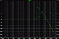
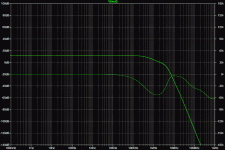
Capacitance of pre-clip zeners shown in final Bode.
I understand stability less every day.
After SRJLH, I thought you would have known better.
Have I ever designed anything that wasn't an oscillator?
I couldn't neutralize Baxandall even in sim, so went
back to CFPs. Q10 and Q20 neuralized by anti-Miller
caps. Q3 & Q4 joined at the collectors, therefore self
neutralized...
Simulated stability in lala land is, so go figure...
However, this one also absolutely hates clipping.
Capacitance of pre-clip zeners shown in final Bode.
I understand stability less every day.
Attachments
-
NeutralizedCircloSomethingOrOther.asc8.2 KB · Views: 51
-
 NeutralizedCircloSomethingOrOther_Open.gif87 KB · Views: 268
 -
 NeutralizedCircloSomethingOrOther_Closed.gif85.2 KB · Views: 266
 -
 NeutralizedCircloSomethingOrOther_Closed_PreClipped.gif87.3 KB · Views: 250
 -
 NeutralizedCircloSomethingOrOther.gif31.8 KB · Views: 245
Last edited:
The third Bode is useless for testing stabilty.
Includes small signal phase shift of the pre-
clip that exists entirely outside the loop.
1st and second Bode plots might be valid?
I can't even guess how QFB mixing interacts.
Includes small signal phase shift of the pre-
clip that exists entirely outside the loop.
1st and second Bode plots might be valid?
I can't even guess how QFB mixing interacts.
It looked intriguing and promising; I knew it wouldn't be plain sailing, but in general I manage to tame anything short of plain positive feedback, but this one seems particularly difficult.What madness possessed you to actually build it???
After SRJLH, I thought you would have known better.
Have I ever designed anything that wasn't an oscillator?
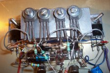
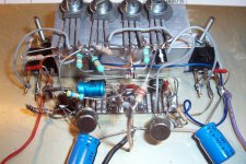
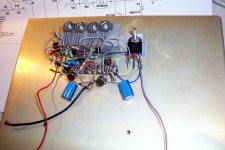
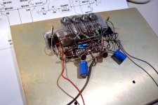
Here are some pics of the prototype, already heavily altered with degeneration/stoppers:
Attachments

There should not be any positive feedback in Baxy LTP
differential mode, but this quadrature feedback is inverse
of Circlophone's. Like SRJLH's shunt tailed pair in disguise.
Even if it appears to "pull" in the normal direction from
underneath, tail current here has the opposite effect.
If something unexpected is happening, I'd look there.
Perhaps a lossy bead somewhere around Q8 is in order?
I know LTSpice hates beads, but they sometimes work.
Last edited:
Did you try #52? PNP emitter faces away from the tail.
I noticed the PNPs had a lot less gain, but neglected to
analyze the real reason why...
Less gain and facing away, either might help fight the
bizarre oscillation, or not...
I noticed the PNPs had a lot less gain, but neglected to
analyze the real reason why...
Less gain and facing away, either might help fight the
bizarre oscillation, or not...
Last edited:
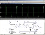
I had a deeper look at the stability and found inconsistencies: depending on where the probe is placed, results can be totally different.
Anyway, the loops are at best metastable, and any event can knock them into instable zones, breaking all hell loose.
It is easy to check in sim by feeding a 1KHz squarewave instead of a sinewave.
It triggers instabilities very much like the ones observed in reality:
Anyway, the loops are at best metastable, and any event can knock them into instable zones, breaking all hell loose.
It is easy to check in sim by feeding a 1KHz squarewave instead of a sinewave.
It triggers instabilities very much like the ones observed in reality:
Attachments
Also if Q8 might shut-off (due to startup, clipping, oscillation),
an absolute blockage of tail current could latch. 10K across CE
Q8 would provide the necessary trickle to get back to normal.
Don't go lower than 2K, as this value or less is also a shut-off.
Tail resistance needs to be a positive value above 2K, but not
so much as to block tail current entirely. Going outside the box
to either extreme will turn all the other transistors off. Either
for lack of tail current or lack of forward bias... This is because
Q6 and Q10 bases have nowhere to conduct in the absence of
a tail current. Unless the emitters Q3 or Q7 were to avalanche.
Perhaps your Q8 is lurching suddenly out of shut-off and going
less than 2K before it knows any better, thus forcing itself (and
everything else with it) back into shut-off?
You built the version with the bootstrap right? If it bleeds more
than reserve current of R11, that too would prevent a latch.
I don't think PNP flavored Baxandall avoids this problem either.
Now you got collectors to avalanche before Q6 Q10 can turn on.
The difference between NPN emitter avalanching at 5V, or PNP
collector avalanche at what, maybe 9V??? A negative resistance
event may not be the wisest method to rely upon for startup and
recovery. So, lets add the bleeder resistor in parallel with Q8.
Last edited:
I am pondering a feature of the balanced CFPs.
That differential collectors summed in the center
will automagically neutralize each other's Miller
without needing to add cross coupling caps.
Which is good, cause adding cross caps doubles
static capacitance to get rid the moving Millers.
Also threatens a weird and evil positive feedback.
Joining collectors together comes with less risk
of such full tentacled madness..
Suppose I make the input pair (with the common
emitter connection) much lower gain, lower shift,
and higher bandwidth by adding emitter resistors
instead?
Now I put all my real gain into common collectors.
I can even Darlington them (grunt end of the CFPs),
and all will neutralize. Yet another half-baked theory...
Only gonna work properly if balanced stage is class A.
We can't return a QFB here, cause one side moving
without the other in true opposition will not neutralize.
And then potentially unstable phase shifts return...
QFB will have to be mixed in after all the balanced
and neutralized gain is done.
Last edited:
I ain't given up, but nothing of late has passed the stability test.
Even when I get a good Bode, the transient goes ape$h*t...
I am messing mostly with a triple Baxandall.. Figuring the extra
stage of inversion could somehow be tricked or neutralized to
cancel some of the madness. Definately not working...
Even when I get a good Bode, the transient goes ape$h*t...
I am messing mostly with a triple Baxandall.. Figuring the extra
stage of inversion could somehow be tricked or neutralized to
cancel some of the madness. Definately not working...
- Status
- Not open for further replies.
- Home
- Amplifiers
- Solid State
- Another of Ken's bizarre circuits