It is stable, but only marginally.
If you remove all your tweaks and replace them with a more classical Cdom scheme, the stability is improved, and the phase characteristic is smoother.
Try two 1nF capacitors between C-B of Q4 and Q6
If you remove all your tweaks and replace them with a more classical Cdom scheme, the stability is improved, and the phase characteristic is smoother.
Try two 1nF capacitors between C-B of Q4 and Q6
Here is "quad core" topology from AD. Termed this way before Intel used it for its processors I ve gathered so far.
Its voltage feedback topology with its positive attributes but with cfb performance. Wide open loop bandwith (far beyond any other voltage feeback topology) and with slew rates similar to cfb. This gives exceptional high frequency THD
Its voltage feedback topology with its positive attributes but with cfb performance. Wide open loop bandwith (far beyond any other voltage feeback topology) and with slew rates similar to cfb. This gives exceptional high frequency THD
Attachments
Circuit of Post #3 with clean power rails: 20K sine, 26VPP out, into 600R.
That is impressive kenpeter. What's the response like?
Reminds of some op-amp I saw recently.
Pair of diamond buffers in tug of war...
Probably some TI thing, I don't recall
which specific part it was.
As for abstracted drawings: Devil is the
proprietary details. Neither you nor they
are showing everything that matters.
Nor giving fair count of discrete parts
needed to DIY.
I also see no current limit upon Q7 Q8,
nor any logic that forces op into class B.
Keeping this stage out of runaway is an
example of such missing detail.
That 5 resistor network in the middle is
wasteful. Needs only 2 resistors crossed
in an X...
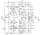
When you flesh out all the abstractions,
it might look something like this: My point
that the new circuit of this thread is much
simpler, especially in the current source
department...
Pair of diamond buffers in tug of war...
Probably some TI thing, I don't recall
which specific part it was.
As for abstracted drawings: Devil is the
proprietary details. Neither you nor they
are showing everything that matters.
Nor giving fair count of discrete parts
needed to DIY.
I also see no current limit upon Q7 Q8,
nor any logic that forces op into class B.
Keeping this stage out of runaway is an
example of such missing detail.
That 5 resistor network in the middle is
wasteful. Needs only 2 resistors crossed
in an X...
When you flesh out all the abstractions,
it might look something like this: My point
that the new circuit of this thread is much
simpler, especially in the current source
department...
Attachments
Last edited:
Absurd inductor for breaking closed loop without losing DC.
I find some series resistance with CDOM makes smoother.
too much or little resistance humps the phase up or down,
away from the flat line near 270 I was hoping to extend.
too much or little capacitance puts the hump in the wrong
place to do the most good. Just right, you won't see much,
just pushes the stability knee out towards the right.
Closed loop bandwidth is still more than 100KHz, and the
20KHz clipping recovery isn't terrible either. 1W distortion
sims 0.0017% at 1W, with 2H and 3H down about -90dB.
If I read this correctly: At 1.3MHz open loop, I have unity
0db gain. I also have -275 degrees phase shift. If +/-360
is an oscillator at 0db, This is 85 degrees phase margin?
Also at -360degrees, I have -44dB. Is that gain margin?
Open loop still required local degeneration in terms of
emitter resistiors to bring the open gain down and slow
the phase roll. Doing it all with CDOM, and/or making
the whole thing more stable than necessary just seems
to slow things down and hurt clipping recovery. So this
soloution represents a compromise.
The phase is flat well beyond audio when loop is closed.
The closed graph is rather boring actually...
Attachments
Last edited:
And the infamous closed loop I recently threatened to bore you with...
Thanks for hammering on me to examine the open loop first.
I don't think I would ever have grasped how it all fits together.
Thanks for hammering on me to examine the open loop first.
I don't think I would ever have grasped how it all fits together.
Attachments

Last edited:
Absurd inductor for breaking closed loop without losing DC.
This inductor trick works, but is not the simplest and most effective solution.
When there is a clear single signal path with a low impedance on one side, and a high impedance on the other, inserting the stimulus in that path is the most direct solution.
You then plot the ratio of the two node voltages.
This version is very conservative, with a large (too large?) plateau at 90°.
It is OK, of course, but maybe unnecessary, and it may impact adversely other aspects.
Increasing the comp further will simply widen the plateau, and not give any improvement in margins, other techniques have to be used for that.
Attachments
Here's another challenge to twist Elvee's mind...
Can he fix and make anything better of it?
Lots of things wrong with this one:
Unstable open loop (slug don't seem to work)
Not very deterministic (edit: try big caps across R2 and R6)
Distortion nothing special
But all the same, there some neat things going here too:
Low dissipation (let resistor get hot instead) high beta shunt drivers!
Insane flat bandwidth before the unstable knee.
The closed loop appears stable with only 10pF.
Where did all the diodes go?
Attachments
Last edited:
The crossing of this one is beautiful: smooth and curvy, the absolute perfection.Here's another challenge to twist Elvee's mind...
Can he fix and make anything better of it?
Lots of things wrong with this one:
Unstable open loop (slug don't seem to work)
Not very deterministic (edit: try big caps across R2 and R6)
Distortion nothing special
The linearity is less satisfactory: there is an open loop gain difference between the Xover region and the "large signal" part of the transfer characteristic.
It can easily be seen by looking at the residue on the inverting input.
It happens because at relatively low output currents, R9 and R10 cause an additional differential NFB path through Q6 and Q8, until they are shunted by the diodes dynamic resistance.
It is probably possible to choose a different set of Iq/R9+10 so that the gm doubling exactly compensates for the gain droop, sort of square law condition.
Compensation is a pain: with a Cdom scheme applied to Q9 Q10 (10nF), it is just stable, but just. The margin is too small to be workable in a real circuit.
Alternatives or complements are certainly possible, but that would require some careful thinking.
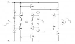
Reminds of some op-amp I saw recently.
Pair of diamond buffers in tug of war...
Probably some TI thing, I don't recall
which specific part it was.
As for abstracted drawings: Devil is the
proprietary details. Neither you nor they
are showing everything that matters.
Nor giving fair count of discrete parts
needed to DIY.
I also see no current limit upon Q7 Q8,
nor any logic that forces op into class B.
Keeping this stage out of runaway is an
example of such missing detail.
That 5 resistor network in the middle is
wasteful. Needs only 2 resistors crossed
in an X...
When you flesh out all the abstractions,
it might look something like this: My point
that the new circuit of this thread is much
simpler, especially in the current source
department...
That circuit is not too far off. 😉
Not that much different from the last schematic I posted.
Merely re-arranged for clarity, fixed some comp problems,
re-biased for lowest distortion (which just so happens to
be as Elvee predicted, square law curve with 1A crossing.)
Then abused resistive part of my tail shunts to double
duty as pull-up and pull-down for output driver shunts.
Those 180R's probably need to be at least 10W apiece.
After adjusting output to 1Vp, and setting rail ripples to
the same, PSRR appears to be around -30db per rail???.
The lump at 1KHz is the 1Vp output, for 0db reference.
Lumps at 100Hz and 120Hz are from the rails. I had to
extend numcycles out to 100 to see the low bins clearly...
And regarding the Bode plots (is that what they are?)
I tried to set them to the same scale. The right edge,
past 10MHz, appears exactly identical. But the closed
loop drops my solid dark gain line down to +12db, and
pushes the dotted phase line upward toward 180deg.
Either way, this appears stable...
Attachments

Last edited:
1W 1KHz distortion is 0.000684%, but this gets worse
as the frequency goes up. There's -10db less open gain
available to burn for linearity at 20KHz, and distortion
at 1W here sims only to be about 0.01%...
Distortion for large signals can be as bad as 0.5%...
Thats not clipping, just plain ol' distortion... GM's
are probably fitting much better than they were,
I guess... but I don't know how to make a set of
wing plots that would readily show those kinks?
Last edited:
Kenpeter do you have a thread where you show some curves for the circuit in post 25. That one looks much more promesing to me. Thats what I was mentioning in post 31.
Kenpeter do you have a thread where you show some curves for the circuit in post 25. That one looks much more promesing to me. Thats what I was mentioning in post 31.
Attachments
You know, regarding stability: The open loop rule might not apply
for the inverting situation? Non-inverting amps can't close a loop
with less than unity gain, output copies the input. Inverting loops
can be closed all the way down to zero.
This fact may reason that an inverting CDOM is added to control
open loop gain and roll for most of our amps. Mindlessly cloning
the same old non-inverting global loop for so long, it is easy to
forget the real purpose why we do things. Was because we had
to guarantee a gain less than unity, we inverted...
These last few inverting amps all had extraordinary bandwidth and
low distortion before I destroyed them with a possibly unnecessary
open loop compensation. I need to review if local slug technique
can truly be replaced by a global slug that rolls below unity before
any of the parasitic poles add a second knee of phase shift?
-------
Inverting loops can be closed all the way down to zero. Output
copies GND. Perhaps I need to look if our situation for GND as
the other input is also stable? I mean, its non-inverting when
you look at it from here, does this mean it can still oscillate?
Or ground is ground, and there is no feedback on this end to
upset it? Damn, I've gone and confused myself....
Last edited:
Stability criteria do apply to inverting amps, the conditions are slightly easier to meet because it has to be stable for G instead of G-1, but for gains of 20~30dB typical of amplifiers, the difference is very small.You know, regarding stability: The open loop rule might not apply
for the inverting situation? .
PS
If you're not convinced by the Bode analysis, you can always test in transient mode, with a very small time step (less than 100ns, like 20ns or even 10ns) and a moderate amplitude square wave output (several volts).
This will reveal any instability or tendancy towards instability in the time domain.
Last edited:
Sumthin' else weird fer Jethro to cipher:
Lets go back to the grossly oversimplified class B.
But this should work for most any inverting amp...
Inverting can be made stable merely by closing
the loop less than unity before the phase rolls
halfway round again. This we already know.
But do we realize that for closed loop gain of less
than unity, we don't have to compensate anything!
NO COMP WHATSOEVER, let me put that in caps...
You never seer this situation with non-inverting,
gain is always over unity, so perhaps it has been
overlooked?
This thing only had a gain of 3.9 before, and not
greatest input impedance. If we assume it wants
for pre-amp anyway, then we should optimize for
output stage duty exclusively.
Setting the gain just less than unity also allows
for very simple pre-clip to the rails. Capacitance
of clipping diodes is also the first roll-off you see.
If you prefer a little less bandwidth, just choose
a different junction, or sandbag a few picos here.
20MHz+ is maybe a little bit overkill, but hey...
Attachments

Last edited:
That is not the case: closed loop gain and loop gain are two different things.But do we realize that for closed loop gain of less
than unity, we don't have to compensate anything!
NO COMP WHATSOEVER, let me put that in caps...
Basically, with a unity gain inverting amplifier, the loop gain will be half of the open-loop gain.
The only way to make an amplifier stable regardless, is on the contrary to increase the closed loop gain beyond the open loop gain.
- Status
- Not open for further replies.
- Home
- Amplifiers
- Solid State
- Another of Ken's bizarre circuits