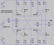
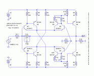
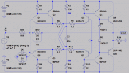
This could be a front end with inverting or non-inverting VAS...
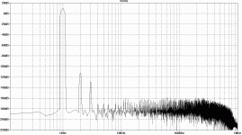
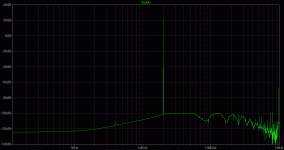
Distortion is really really low, given the simplicity and nothing
fancy parts. Second harmonic -120db down for smaller signals.
Anyways, mo' crazy abuse of shunt tail pairs. Resistor provides
an excess of unregulated the tail current. And CFP shunt regs
divert away all the low class electrons, leaving only the tastiest
regulated currents. Or some high scientifical nonsense like that...
Adds some gain in the process. Or more truthfully, pushing the
balance of existing gain unfairly toward the output side of the
pair. Thus shunt tail pair output current gain appears doubled.
I am kinda preferring the inverting version as shown. Holds
input transistors at constant voltage and current. No need for
cascode. And you get to push rails a little further apart for the
same VCE max. This is all because comparison to GND keeps
the input stage stationary between the rails.
Don't worry .models, its all in there. Just cropped the picture...
Attachments
Last edited:
Nah: maybe this is load tolerance, 400WRMS into 2ohms?
Mind you, won't go lower than 5Hz without violating SOA.
Brands might differ where the 100mS line theoretically is.
I am not recommending 2ohm load for this transistor.
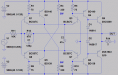
Lets look the schematic for a sec: I got rid the 8K2 on
the GND side. Why? Cause it might double offset instead
of cancelling, issue of inverting. I could be wrong here,
its not something I've thought long enough to be sure...
Getting rid the 8K2 makes a little unstable, not sure why.
But adding a 47u fixes that, and generally helps in every
way that I can determine. Even if you leave the 8K2, the
new 47u should probably stay.
If you bias an output for Class B, you can Muntz out a
great many emitter resistors all around. The feedback
loop assures nothing will run away, as long the output
doesn't short. If output short happens, game over...
Warn: This sim includes some noise on the power rails
Attachments
Last edited:
As for Elvee's mod, violates some of my pet concerns that may not matter.
I would just add a diode to the input side to keep collector voltages same.
Then again, I am also about to claim that imbalance was to our advantage.
Certainly more linear open loop in CFP vs CFP balance, but half the useful
gain of that stage is pushed back. Open loop gain improves only because
a transistor got added. I suspect we could add this same gain without re-
balancing the shunted pair and throwing half of it away. But we close the
big loop and this extra gain is going to be thrown away anyhow, so the
distinction of where gain gets sacrificed to linearity is a mere preference.
If closed linearity ends same, I'd just go whichever way used least parts.
Last edited:
Probably acts as a base stopper: generally, such a resistor interact with B-C capacitance of the transistor and acts as a self compensation.Nah: maybe this is load tolerance, 400WRMS into 2ohms?
Mind you, won't go lower than 5Hz without violating SOA.
Brands might differ where the 100mS line theoretically is.
I am not recommending 2ohm load for this transistor.
Lets look the schematic for a sec: I got rid the 8K2 on
the GND side. Why? Cause it might double offset instead
of cancelling, issue of inverting. I could be wrong here,
its not something I've thought long enough to be sure...
Getting rid the 8K2 makes a little unstable, not sure why.
Except of course with "funny" circuits, like the Xquad, where it has the opposite effect (BTW, I stumbled upon the prime originator of this delightful circuit: it's a guy called Raimondo Caprio, and he invented it back in 1973).
That's strange: it probably prevents some kind of side mode mixing/conversion, but it shouldn't have a dominant effect on stability.But adding a 47u fixes that, and generally helps in every
way that I can determine. Even if you leave the 8K2, the
new 47u should probably stay.
It could have an impact on linearity though, particularly on even order harmonics.
I think it could be a nice class A driver, but a 10K load limitation for good performances is too restrictive. 1K or 600 ohm is more realisticIf you bias an output for Class B, you can Muntz out a
great many emitter resistors all around. The feedback
loop assures nothing will run away, as long the output
doesn't short. If output short happens, game over...
Circuit of Post #3 with clean power rails: 20K sine, 26VPP out, into 600R.What's the performance at 20k say 12 or 13v pk into 600 Ohms?
Attachments
Last edited:
The 1µs timestep doesn't do justice to the circuit's performance.Circuit of Post #3 with clean power rails: 20K sine, 26VPP out, into 600R.
But on the other hand, when it is shortened under 500ns, it unveils instabilities.
It can be cured by reintroducing the 8K2 resistor.
Attachments
nope it svings in a rather spiky way....made some feedback into the input transistors and reduced gain to 8 db with at supply of 18 V.. inserted current-sources for instead of rail-resistors...magnificent Pre-amp with distortion at -140dB...at 4 Volts out PP...but it inverts...🙁
Member
Joined 2009
Paid Member
Second harmonic -120db down for smaller signals.
Wow, that's really tiny - somebody gotta build it....
Elvee what is this xquad circuit, same as analog devices "quad core or otherwise named H bridge (ad8047). This circuit actually reminds me of the operation of that said circuit except the way the biasing is done.
XQuad:
Its negative impedance slope, positive feedback,
infinite open loop gain, impossibly unstable, and
unfortunately reminds of how this circuit behaves.
I think maybe the CFP's feel pfb somehow.
Its considerably more stable with 0R1 sample
of the output collector nfb to the input emitter.
Resistor on the opposing emitter of the pair
must scale up with deliberate gain imbalance,
else you add an offset error. Since I find 9mA
in my small transistor, and 100ma in my driver,
9/(100+9) I must use about 0R1/1R2 ratio.
The bigger resistor with the smaller current...
I mean, if you are going to add resistors here for
local degeneration, the offsets must match. When
you sample CFP collector current for one side only,
the sample for that side will be larger by whatever
amount leaks down the resistive tail.
Last edited:
Elvee what is this xquad circuit, same as analog devices "quad core or otherwise named H bridge (ad8047).
No, the Xquad is an ideal "transconductor", see explanations here:
http://137.110.119.31/papers/2007_10.pdf
As Ken said, in its raw form, it is a powerful but fractious beast.
It can be tamed however: on this forum, the great Eva has proposed a better behaved version, when she was still interested in analogue design.
http://www.diyaudio.com/forums/solid-state/189599-my-little-cheap-circlophone-22.html#post2693558
I have also published a zero-NFB headphone amplifier using a modified Xquad as voltage gain stage, the Tringlinator:
http://www.diyaudio.com/forums/head...glinator-mos-based-tringlotron-amplifier.html
It can be tamed however: on this forum, the great Eva has proposed a better behaved version, when she was still interested in analogue design.
http://www.diyaudio.com/forums/solid-state/189599-my-little-cheap-circlophone-22.html#post2693558
Uhm, that thread has 760 posts.
Did the circuit in post 1 survive the discussion or is there a more definitive version to be found further on in the discussion?
The permalink leads you directly to post #215, where the relevant information is to be found.Uhm, that thread has 760 posts.
Did the circuit in post 1 survive the discussion or is there a more definitive version to be found further on in the discussion?
No, that version is still the current one.
I made a dual shunt feedback with quite low values...that thamed the circuirt quite well added a few pF over the feedback resistor to limit bandwith a bit...in sims the swing was at app 100 MHz...
Is this a stable closed loop? For inverting, what exactly is the rule?
I would like to do this without pushing 2nd harmonic up to -90db.
Remind you, 2H was -120db before all this tweaking for stability.
Can make even better looking .ac analysis with ferrite beads, but
.tran still goes banannas. Not sure why LTSpice loops hate ferrite?
Using only caps and resistors, this is best I could come up with...
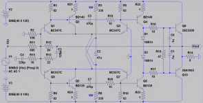
c3 c4 form a capacitive voltage divider, sets HF gain less than 1.
Much less shifty than high pass cap in the feedback alone.
c5 c7 sabotage both the unbalanced differential pairs and the
CFP shunt tails, such that they do less or nothing at HF. Again
with very low shift...
C6 C1 roll off a strange peak that otherwise exists exactly at
100MHz, and probably just some mathematical artifact of sim.
Attachments
Last edited:
- Status
- Not open for further replies.
- Home
- Amplifiers
- Solid State
- Another of Ken's bizarre circuits
