That's an Apple remote.
If you change your mind about coding (you really should) there's lots of useful info here: Apple Remote | H i F i D U I N O
/U.
If you change your mind about coding (you really should) there's lots of useful info here: Apple Remote | H i F i D U I N O
/U.
I havent messed around with it in a while but I would still like to figure out how to save the volume setting...
Other than that it is performing flawlessly...and sounds good too.
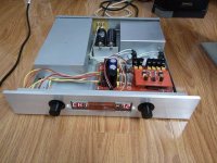
Running 6h30 input tubes and 5687 outputs on the Aikido portion. PSU is a Broskie PS-1 with CRC B+ and regulated heater supply.
Other than that it is performing flawlessly...and sounds good too.
Running 6h30 input tubes and 5687 outputs on the Aikido portion. PSU is a Broskie PS-1 with CRC B+ and regulated heater supply.
Haven't gotten that far in my Arduino-experiements myself, but you need store the volume levels in the EEPROM instead of in standard variables. Start here 🙂
Arduino - EEPROMWrite
/U.
Arduino - EEPROMWrite
/U.
Into this:
Hi,
This is almost the same concept that I want build in next days. Have you any new progress on this?
OK making a little more progress...
Working:
- So far I changed the welcome message
- I got rid of the volume bar thing that didnt display right
- On the remote the left button toggles the input 1 on/off
- The right button toggles input 2 on/off
- The top button is volume up
- Bottom button is volume down
Still need to fix:
- On the display I tried to get it to display which input is active to the right of the startup message. The input shows and stays on until you adjust the volume and it goes away.
- The ability to scroll through the inputs just by pressing left or right buttons
- Add a mute function by pressing play/pause - just need to assign function to button and pin on arduino board
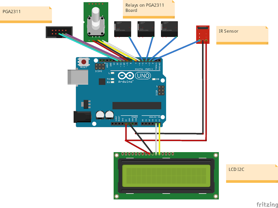
- Need to add encoder
Here is the latest functioning code:
Code:/* Arduino pins: - digital pin 13 (SCK) = SPI SCLK (PGA2311 pin 6) - digital pin 12 (MISO) = not used - digital pin 11* (MOSI) = SPI SDI/MOSI (PGA2311 pin 3) - digital pin 10* (SS) = SPI \CS (PGA2311 pin 2) - digital pin 6* = IR receiver data - digital pin 1 = not connected - digital pin 0 = not connected * is a PWM pin /*-----( Import needed libraries )-----*/ #include <Wire.h> // Comes with Arduino IDE // Get the LCD I2C Library here: // https://bitbucket.org/fmalpartida/new-liquidcrystal/downloads // Move any other LCD libraries to another folder or delete them // See Library "Docs" folder for possible commands etc. #include <LiquidCrystal_I2C.h> #include <IRremote.h> #include <stdlib.h> #include <SPI.h> /*-----( Declare Constants )-----*/ /*-----( Declare objects )-----*/ // set the LCD address to 0x27 for a 20 chars 4 line display // Set the pins on the I2C chip used for LCD connections: // addr, en,rw,rs,d4,d5,d6,d7,bl,blpol LiquidCrystal_I2C lcd(0x27, 2, 1, 0, 4, 5, 6, 7, 3, POSITIVE); // Set the LCD I2C address /*-----( Declare Constants )-----*/ #define RELAY_ON 0 #define RELAY_OFF 1 /*-----( Declare objects )-----*/ /*-----( Declare Variables )-----*/ #define Relay_1 2 // Arduino Digital I/O pin number #define Relay_2 3 #define Relay_3 4 /*IR detector data=pin 6 * PGA2311 gain: N = 1 to 255 * Gain (dB) = 31.5-[0.5*(255-N)] * SPI interface: * /CS (pin 2) * SCLK (pin 6) * SDI (pin 3) * SDO (pin 7) */ const int slaveSelectPin = 10; int RECV_PIN = 6; IRrecv irrecv(RECV_PIN); decode_results results; String lastIRoperation; int relay1 = 2; int relay2 = 3; int on = 0; int on1 = 0; int on2 = 0; char cGain[17]; String gain; char icGain[6]; float iGain = -95.5; float nGain = 1; void setup() { Serial.begin(9600); // Used to type in characters lcd.begin(16,2); // initialize the lcd for 16 chars 2 lines, turn on backlight lcd.write("CJ's Preamp "); irrecv.enableIRIn(); pinMode(slaveSelectPin, OUTPUT); SPI.begin(); //-------( Initialize Pins so relays are inactive at reset)---- digitalWrite(Relay_1, RELAY_ON); digitalWrite(Relay_2, RELAY_OFF); //---( THEN set pins as outputs )---- pinMode(relay2, OUTPUT); pinMode(relay1, OUTPUT); delay(4000); //Check that all relays are inactive at Reset } int VolumeUp() { if (nGain < 255) { nGain = nGain + 1; setGain(nGain); setVolumeBar(nGain); } else { lcd.setCursor(0, 0); lcd.write("Maximum Reached"); delay(500); } } int VolumeDown() { if (nGain > 1) { nGain = nGain - 1; setGain(nGain); setVolumeBar(nGain); } else { lcd.setCursor(0,0); lcd.write("Minimum Reached "); delay(500); } } void setGain(int nGain) { digitalWrite(slaveSelectPin,LOW); SPI.transfer(nGain); // right channel SPI.transfer(nGain); // left channel digitalWrite(slaveSelectPin,HIGH); } void setVolumeBar(int nGain) { // convert gain to a decibal string, and write to the lcd iGain = 31.5 - 0.5*(255 - float(nGain)); gain.toCharArray(icGain, 6); dtostrf(iGain,4,1,icGain); gain = String(icGain); lcd.clear(); lcd.write("CJ's Preamp "); ("Volume: " + gain + " dB").toCharArray(cGain,17); lcd.setCursor(0, 1); //first line lcd.write(cGain); // write the volume bar } unsigned long last = millis(); void loop() { // Decode the IR if recieved if (irrecv.decode(&results)) { if(results.value == 2011254788) { lastIRoperation = "volumeUp"; VolumeUp(); } if(results.value == 2011246596) { lastIRoperation = "volumeDown"; VolumeDown(); } if (results.value == 2011271172) { // Remote Control Power Code // If it's been at least 1/4 second since the last // IR received, toggle the relay if (millis() - last > 250) { on = !on; digitalWrite(relay1, on ? HIGH : LOW); lcd.setCursor(13,0); //Start at character 13 on line 0 lcd.print("IN1"); } last = millis(); } else if (results.value == 2011258884) { if (millis() - last > 250) { on1 = !on1; digitalWrite(relay2, on1 ? HIGH : LOW); lcd.setCursor(13,0); //Start at character 13 on line 0 lcd.print("IN2"); } last = millis(); } if(results.value == 4294967295) { if (lastIRoperation == "volumeUp") { VolumeUp(); } if (lastIRoperation == "volumeDown") { VolumeDown(); } } irrecv.resume(); // Receive the next value } }
Hi, I try to use this code but I get a lot of error!!!
I must fix something?
thanks


its cool project,
It would be great if we could support SI4703 in this project.
with a few preset buttons and a Tuning encoder.
I can do the testing if needed.
It would be great if we could support SI4703 in this project.
with a few preset buttons and a Tuning encoder.
I can do the testing if needed.
Last edited:
Hi Terranigma
Have you finished the build of the pga23xx, would like to use it with the circlophone if you could share
Regards
Aditya
Hi,
This is almost the same concept that I want build in next days. Have you any new progress on this?
Have you finished the build of the pga23xx, would like to use it with the circlophone if you could share
Regards
Aditya
- Home
- Source & Line
- Analog Line Level
- Another Modified PGA2311 kit with Arduino for volume control and input selection