This is another method to set up a digital controlled voltage supply.
I want to use a DAC and a Operational Amplifier. I want to use the LTC 2609 and control the output of DAC from 0 to 5V. Operational Amplifier I want to use the OPA541 which can provide -35V to +35V output and the maximal output current is about 2A. This is the circuit pic.
I have few experience on that, So could anyone help me check the circuit up to see whether there are some problems in it. Thanks a lot!!
Attachments
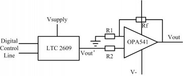
It's a bit rough, isn't it? ;-) Assuming R1 is at the inverting (-) input, this will basically work. Caveats:
* Do check out the OPA541's price tag before you commit to this circuit - there's a price to be paid for "simplicity".
* The LTC2609 is a quad DAC. Obviously, if you intended to use all four channels to drive OPA541s, the outputs must share a common ground. You'd still be well advised to include opto-isolation between the DAC and the computer, to protect the latter.
* Your initial choice of digital pots was going to give 10 bit resolution, now you pick a 16bit DAC; depending on actual needs, there may be cheaper parts than the 2609 also.
* The 2609 needs an external reference; the supply is usually not good enough for that (for sure not if you need anything over 10 bits). While it is specified as rail-to-rail output, Vref must not exceed Vcc; the typical application would run Vcc=5V Vref=4.096V (there are some reference chips for that "odd" value); this yields 1/16 mV resolution (not accuracy), times the OPA541's amplification.
* Remember to compensate for offset values somewhere - since the 2609 is unipolar, doing it digitally may not work and a trimpot could be a better choice. Span can be calibrated digitally.
* Look closely at the OPA541 data sheet for current limiting (it wants an external resistor for that); use output protection diodes; put 100n blocking capacitors close to V+ and V-; and check that you're inside the SOA + cooling requirements. You may also need extra compensation.
* If you're looking for positive outputs only, you can run the OPA on asymmetrical supplies, see datasheet example Fig. 6 (+60/-8V).
* Note voltage drop on OPA = 4.5V@2A, 5.5V@5A per data sheet.
For wine&dine
Thank you again for so detailed reply.
Yes, the price is so expensive!! Why? OPA541AM is $US96.2,but the OPA541AP and APG3 is about the $US11.1. Why the difference is so large!!?? The "lead time" means that I have to wait that time for the products??
Maybe I should use the OPA544 which is much cheaper!!
OPA544 and OPA541 have not pin for offset trim, so how can I do that?
A good news, I just know that I have labview which can provide four DAC line by a card. So now I need not consider the DAC. Four is enough for me now. In the future I will need that.
So if I want use the DAC I have to add a operational amplifier between them? like the OPA602 in the pic I attached?
Your suggestion about the digital pots is right. I think the 10 bits is ok for me.
But I think most the DAC need a external reference, Maybe I should use a voltage regulator.
Now I have not found how to use the SOA. I think tomorrow I will get it.
Yes, I only need the opsitive output, So if I use the OPA544, Can I use the same asymmetrical supplies like OPA541? I did not see the same figure in OPA544's datasheet.
Now I want a large output voltage, I hope can get the 100V output. But I googled and did not find that high output voltage op-amp. Do you know is there some chip or device can provide that voltage? or is there some other solutions? I saw a figure in LM143's datasheet which can provide 130V p-p. But I think I can not use that, because there is no absolute ground.
Thanks a lot!!
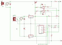
Attachments

That extra opamp in the circuit you posted is needed only because the DAC in question has a current output. You were considering voltage-out DACs or D-pots, so you don't need it.
The LM143 has an output voltage swing of +-37 V only. (You'd be using an LM343 anyway, that's the commercial-grade part).
For offset trim, attach the ground side of the feedback resistor to a trimpot between +10/-10 mV.
You CAN buy opamps to do 100V output directly, see e.g. http://eportal.apexmicrotech.com/mainsite/products/linvoltage.asp which lists parts up to 1140V p-p output - but again, fasten your seat belt before asking for prices. It's the old make vs. buy tradeoff here.
>most the DAC need a external reference,
>Maybe I should use a voltage regulator.
You should use a voltage REFERENCE, which has been designed for lower tolerances and temperature drift. That's what VR1, a TL431, does in my circuit - with R4=R5=10k, it holds +5V across R6.
> I think I can not use that, because there is no absolute ground.
Since you already have a DAC card, you can also use analog isolation. Set your card to 0-5V out, stick an ISO124 (http://focus.ti.com/docs/prod/folders/print/iso124.html) at each output, and use the isolated output of the ISO124 as the reference in your output stage without having to worry about ground levels.
In my floating circuit, omit R3, R4, R5, VR1 and feed the ISO124 output to the left side of R10. Attach R8 to +12V and use a trimpot or fixed value for R7 to set current limit. Leave out the current limit stuff but don't complain to me when you make it smoke ...
(Again, that circuit will happily handle 100V or more if B1/C1/T1 are up to it.)
Oh BTW, you can also look at how the pros do it - Keithley makes several products with a +-100V source and some manuals (DL from keithley.com) have schematics, e.g. 230_901_01H.pdf page 61. They essentially build their own HV OPAMP. Nice, but NOT simple ...
Thank you for your suggestion.
I found the Op-amp PA240CC&CX is $19.65, whose supply voltage is about the 350V, and the output current is about 60mA. So it is enough for us.
What confuse me is that the PA241CE&CEA&CEM's price are $55 $74 and $145 repectively. The function of the PA241 and PA240 are almost the same! But the price is so different. Is that just because the different package?
If I want to use PA240CC or CX, I shoud consider ISO124, offset trim, add some capacitors to the voltage supply of the Op-amp, input voltage protection, SOA, add some heatsinking. Is there any other things or problems I should consider?
I think another choice is PA78DK, the price is not very high,about $25.5.
So if I can use the high voltage Op-amp, the circuit will be more easy for me. And we need at least six voltage supply, so if I have to do a complex circuit, it will be a large project. But we just want to test our device more easily.
So if I can use the high voltage Op-amp, the circuit will be more easy for me. And we need at least six voltage supply, so if I have to do a complex circuit, it will be a large project. But we just want to test our device more easily.
I saw the OPA541 can be use the asymmetrical supplies to get 0 to 50V output voltage. Can any other Op-amp do that? How can we make sure the asymmetrical supplies voltage(like 60 and -8V for OPA541)?
Now we think the most suitable device for us is PA240CX. Because firstly the price is cheapest(less than $19), secondly it can be used from 0 to 160V at least and that is nice for us, thirdly its legs looks like more easily used on breadboad.
But now I found that it is a little difficulty to find a DC supply which can provide +175V and -175V at the same time. So is there some products about that? Or I should use the bridge fectifier and capacitor to be a supply?
If we set up the circuit on the breadboad, is that reliable for a long time using?
And do you think that can work?
It's YOUR assignment, not mine, so why don't you do some homework?
I don't know about your breadboard techniques; I regularly build stuff on epoxy perfboard to last forever.
READ THE DATA SHEEETS! With +-175V, you're going to fry the poor opamp for nothing. The PA240 has a 350V ABSOLUTE MAXIMUM rating.
Oh BTW: Notes: 4. Since the PA240 has no current limit, load impedance must be large enough to limit output current to 120mA.
You said you needed positive output only - give it an asymmetric supply. Note input common mode range is (-Vs + 12) to (+Vs - 14) volts, output swing about the same. IOW, something like -30/+X Volts would work. Limit V+ to what ever you need to avoid useless power dissipation = heating.
An example supply using off-the-shelf parts: Transformer with 4 x 33V secondaries (or two duals). Use one for negative, three for positive, gives +140/-45 Volts DC unregulated, perfect for 100V out. (See elsewhere around here for discussions about +/- supplies with one bridge, note the two legs need not be symmetrical).
Note: You'll be dealing with dangerous voltages; make sure you read up on safety (check over in the tubes forum) and have someone competent check your design before you go live. That means physically being there to see how you built it.
One more note - this is an opamp circuit. Capacitive loading of the output will make it oscillate without further compensation.
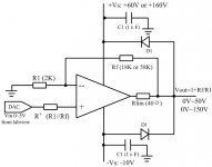
a little detailed circuit schematic about digital control voltage supply
At last, I chose the PA69EU which have current limitation, and the package is more easily to use on breadboard. Of cause the price is not very high.
I design the two set of output voltage: 0~50V and 0~150V;
DAC is from labview card and output is from 0~5V;
R' is to make the plus amd minus input resistance the same, I don't know whether I need that?;
R1=2K, Rf=18K for 0V~50V output, Rf=58K for 0~150V output;
-Vs=-10V is enough for input common mode voltage limitation, I want to contact the plus output of DC power supply to the ground and the minus output to -Vs pin;
C1 is power supply bypassing, I chose that C1=1uF, which is decide by 10uF/peak output current. Here I don't know whether I need another capacitor for high frequency bypass, because I think I only work at DC condition?;
Rlim is difined by SOA of the PA69EU, but the graph on the datasheet is only TBD, ft,so I just estimated a value by Ilim=10mA: Rlim=0.4/Ilim, 0.4 is for 125C working temperature;
D1 is flyback diode, I don't understand what is the fast recovery diodes? datasheet said that it's recovery times should less than 100 nanosecond.;
Another question confused me is whether I need a RcCc network to improve the stability of the Op-amp. Because my circuit only work in the DC states. I think I don't need that.
Is there anything that I should consider? Thank you very much for anyone help me check up the circuit!!
Attachments
1. I may have said it before ;-) ISOLATE from the PC.
2. Recommended practice for bypassing power opamps is to combine electrolytics (but larger than 1uF, say 10-100) with ceramic 100nF for low impedance at higher frequencies.
2.
>my circuit only work in the DC states. I think I don't need
>[a compensation network]
Oh my. You may choose to only *feed it* slow-moving signals. It still amplifies *AC*.
Read up on http://www.ecircuitcenter.com/Circuits/op_cload/op_cload.htm
Thank you for your suggestion about the power bypassing capacitor, I will do that.
To isolate from PC, I may use the ISO124.
Is it possible to connect the DC power supply's plus output to groud and connect the minus output to -Vs? To get a -10V supply.
To isolate from PC, I may use the ISO124.
Is it possible to connect the DC power supply's plus output to groud and connect the minus output to -Vs? To get a -10V supply.
>Is it possible to connect the DC power supply's plus
>output to groud and connect the minus output to -Vs?
>To get a -10V supply.
If you are asking whether you can combine a +100V supply (between V+ and ground) with a +10V supply (between ground and V-) to get +100/-10, then the answer is YES, as long as the supplies are galvanically isolated against each other (separate transformers or separate secondaries).
Small transformers are cheap, and your current requirements are moderate, so just use 2 transformers per channel to get complete isolation.
Again: Careful above about 50V!
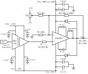
The updated circuit schematic.
Under your advise, this is the new updated circuit schematic. If you have time, please help me check that. Thanks!!
For ISO124, in its datasheet, there is a requirement that the minimum input voltage range is +-10V, so can I input the signal less than 10V? Or can I use a voltage follower to isolate the PC DAC card from Op-amp?
To trim the offset voltage, I use a adjustable resistance(adjustable potentiometer) R3 which bias from +1V to -1V. Is there any problem for offset trim?
For RcCc network, I use Rc=100 ohm and Cc=33pf for 50V output and 11pf for 150V output.
C1 is ceratic capacitor and C2 is electrolytic capacitor. D1 Cc C1 C2 all can afford 200V.
Because I need at least four voltage supply, and each one's current requirement is not high. So can I use one DC power supply for four or 6 Op-amp?
Thank you for reminding several times to be careful about high voltage. I will appreciate to you if you can tell me some webside about that.
Is there some other problems about the power supply circuit?
Thank you very much!!
Attachments
>The updated circuit schematic.
We're getting there ... eventually ;-)
>For ISO124, in its datasheet, there is a requirement that
>the minimum input voltage range is +-10V, so can I input
>the signal less than 10V?
Of course. But there's one fatal flaw in your circuit - the ISO124 is supposed to provide galvanic isolation between the PC and the output stage; that means, you have to power its input side from the PC and the output side from the output stage, not both from the latter. Note you only need +/- 5V for the input side (see also data sheet Fig. 9), which are readily available in your PC.
>To trim the offset [...] bias from +1V to -1V.
Voltage span is much too large. Compare offset specs of power opamp. Just use a divider circuit.
Look up http://www.analog.com/library/analogDialogue/archives/39-05/op_amp_applications_handbook.html
Chapter 1 p.9 discusses external offset trimming.
>Because I need at least four voltage supply, and each
>one's current requirement is not high. So can I use one
>DC power supply for four or 6 Op-amp?
You can, but of course it means that the outputs will have one common ground. Even if this is OK for your current application, consider that the device would be a lot more flexible if the outputs were separate - all it costs is a couple of cheap little mains transformers, diodes and caps; the ISO124s already provide the galvanic separation.
>careful about high voltage [... website]
Look right here on this site over in the Tubes forum.
- Status
- Not open for further replies.
- Home
- Amplifiers
- Power Supplies
- another method to set up a digital controlled voltage supply which can provide 0~30V