Hello all,
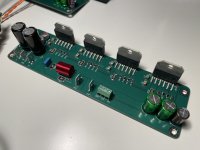
Excited about my latest revision of the LM3886-based amplifier!
Initially, I was thinking of putting two of them in parallel, but then it was three, and later on, it became four lol. The reason is that I want to bridge two channels and thus quadruple the power to 200W (or 400W into 4R).
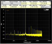
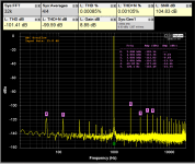
So far, using a 25V-0-25V transformer, I was able to get 100W into a 4R load with very low THD+N of 0.00142% @ 1kHz. THD is even lower at 0.00135%.
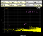
The 8R load showed even more impressive results of 50W at 0.00047% THD or 0.00066% THD+N.
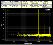
10kHz measurements are also attached.
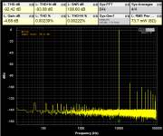
It is argued that the most realistic test for the amplifier is running a 1kHz tone into a 4R load at 5W of output. Such a test is attached too and results in 0.00085% THD or 0.00105% THD+N.
One of the goals for this build was to achieve very low distortion, especially at frequencies higher than 1kHz. Many commercial amplifiers optimize for 1kHz performance, as this is usually what is being measured by the reviewers. With my build, I wanted to optimize for great performance across all frequencies.
Granted, mine is more of a brute force approach to reduce distortion by adding more chips in parallel. I recognize that at some point, such an approach will hit a point of diminishing returns where by adding more chips the distortion will not be reduced.
Listening tests will follow.
Edit:
Listening Tests
I'm delighted to report that I've confirmed exceptional measurement results through three days of listening to the amplifier.
What's especially noteworthy is the level of resolution—I’m picking up nuances in the music that were previously less apparent. Clarity is another standout feature, with soft yet distinct high frequencies and excellent resolution and spaciousness in the midrange.
The low end leans towards the softer side. Compared to the Modulus-86, the low end is gentler and less pronounced, whereas the Modulus-86 amp has a punchier low end.
Edit:
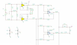
Attached is schematics in Tina-TI to illustrate the idea behind the amp. Input unity buffers are implemented using OPA1656, as they are capable of providing sufficient current drive for the LM3886s. This results in much cleaner highs, pleasing mids, and a "black" background.
Excited about my latest revision of the LM3886-based amplifier!
Initially, I was thinking of putting two of them in parallel, but then it was three, and later on, it became four lol. The reason is that I want to bridge two channels and thus quadruple the power to 200W (or 400W into 4R).
So far, using a 25V-0-25V transformer, I was able to get 100W into a 4R load with very low THD+N of 0.00142% @ 1kHz. THD is even lower at 0.00135%.
The 8R load showed even more impressive results of 50W at 0.00047% THD or 0.00066% THD+N.
10kHz measurements are also attached.
It is argued that the most realistic test for the amplifier is running a 1kHz tone into a 4R load at 5W of output. Such a test is attached too and results in 0.00085% THD or 0.00105% THD+N.
One of the goals for this build was to achieve very low distortion, especially at frequencies higher than 1kHz. Many commercial amplifiers optimize for 1kHz performance, as this is usually what is being measured by the reviewers. With my build, I wanted to optimize for great performance across all frequencies.
Granted, mine is more of a brute force approach to reduce distortion by adding more chips in parallel. I recognize that at some point, such an approach will hit a point of diminishing returns where by adding more chips the distortion will not be reduced.
Listening tests will follow.
Edit:
Listening Tests
I'm delighted to report that I've confirmed exceptional measurement results through three days of listening to the amplifier.
What's especially noteworthy is the level of resolution—I’m picking up nuances in the music that were previously less apparent. Clarity is another standout feature, with soft yet distinct high frequencies and excellent resolution and spaciousness in the midrange.
The low end leans towards the softer side. Compared to the Modulus-86, the low end is gentler and less pronounced, whereas the Modulus-86 amp has a punchier low end.
Edit:
Attached is schematics in Tina-TI to illustrate the idea behind the amp. Input unity buffers are implemented using OPA1656, as they are capable of providing sufficient current drive for the LM3886s. This results in much cleaner highs, pleasing mids, and a "black" background.
Attachments
-
 100W_1khz_4R.PNG37.1 KB · Views: 431
 -
 1khz_53w_zeroed_graph_8R.PNG39.4 KB · Views: 268
 -
 100W_10khz.PNG36.5 KB · Views: 245
 -
 10khz_53w_zeroed_graph.PNG36.7 KB · Views: 237
 -
 5W_1khz____scaled___4R.PNG38.6 KB · Views: 340
 -
 IMG_2798.jpeg284.5 KB · Views: 371
 -
 IMG_2799.jpeg368.2 KB · Views: 351
 -
 IMG_2800.jpeg376.5 KB · Views: 436
 -
 IMG_3226.png17.8 KB · Views: 295
Last edited:

From my experience lowering amount of components and thus complexity for LM3886 allowed for lowest distortion possible.
Previously I tried using servo schematics like in TI app note but complicated layout resulted in higher distortion. Using LM3886 in true balanced topology allowed to minimize offset errors and servo was no longer required.
More reading here - https://hifiocean.com/blogs/news/differential-configuration-for-lm3886
I am not using so called “stability components “ from TI data sheet either - including them did not look good on a square wave test. Talking about series RC network over the feedback resistor and C in parallel with inputs.
Is it mainly for driving low impedance?
Read that in parallel there are currents vagabonding?
In practice an existent problem?
Read that in parallel there are currents vagabonding?
In practice an existent problem?
The Chinese board has servos to synchronize the amps. The LM3886 has been in production a long time, I think if you get all from one production batch, they should be identical and not need it. An .22 Ohm resistor in the output of each LM should match them up. If you buy mixed up chips from unsecure, different sources, maybe recycled as most stuff on Alibaba, this may not work.
The 6x version has the bridge converter included in the design and servo's each amp. It can be safely driven with a higher voltage than the 4x and deliveres more power. If it works at all!
The 6x version has the bridge converter included in the design and servo's each amp. It can be safely driven with a higher voltage than the 4x and deliveres more power. If it works at all!
😱, packs of 6 built in active bass 🤣

Only 0.1 ohm at each output, no DC servo, important is to use 0.1% resistors in feedbacks of parallels, 0.01% even better. Rest of PS is not on picture, golden caps are just local decoupling
Only 0.1 ohm at each output, no DC servo, important is to use 0.1% resistors in feedbacks of parallels, 0.01% even better. Rest of PS is not on picture, golden caps are just local decoupling
If you wish I have pcb diagram but only in dwg for Autocad, at that time I did not have pcb dedicated CAD. 2 things can be improved on that board but I didn't bother as it's used for bass only.
Most important is that it's stable, and makes easy 300+ watt in 4 ohms
Most important is that it's stable, and makes easy 300+ watt in 4 ohms
I am using QA403 audio interface.What noise floor your sound card have in closed loop?
There are 8 different settings for the input attenuation:
0, 6, 12, and 18 dBV
24, 30, 36, and 42 dBV
To measure output of 5W or with 8R load => Vrms of 6.32 I used 24 dBV attenuation.
I did not do loopback measurements for the interface itself yet.
The LM3886 has been in production a long time, I think if you get all from one production batch, they should be identical and not need it. An .22 Ohm resistor in the output of each LM should match them up. If you buy mixed up chips from unsecure, different sources, maybe recycled as most stuff on Alibaba, this may not work.
Only 0.1 ohm at each output, no DC servo, important is to use 0.1% resistors in feedbacks of parallels, 0.01% even better.
I wonder about the value of the load-sharing resistors required. Matching between ICs is not well-controlled. I expect the current sharing resistors have to be larger than with just BJTs.
Ed
Hi Ed,
I can say only for what I built and it works, lot of 14 (2 I have spare) lm3886 was bought from Distrelec in Switzerland and they appear to be from the same lot.
I would avoid by any means using chips from different lots/shops in parallel. Like this, 0.1 ohm is enough, mine blocks are not heating on idle at all, and I did not measure any current through these load sharing resistors without signal. What I believe does matter is to match feedback resistors as close as possible, to extreme precision. It's simple math that even slightly different gains will produce high internal currents between chips when driven. But if this is taken care off, it works as per application note.
Three ways to optimize paralled LM3886:
1. Matching chip-amp ICs, ensuring that they are identical or come from the same manufacturing lot to minimize variations.
2. Matching the gain between each chip-amp, ensuring equal amplification across all branches of the circuit.
3. Optimize ballast resistors. These external resistors added to each chip-amp's output and balance the load for more equal distribution of the current.
To sove #1 just buy multiple ICs from say Mouser or directly from TI.
For #2 use 0.1% resistors.
For #3 use 1% 0.1R 0.22R or 0.33R
As an example for two LM3886 chips we can calculate all the parameters below:
For 1% tolerance gain resistors, there are four permutations:
Gain variations for all four cases:
To remedy such a situation, 0.1% resistors should be used. To improve even further, the ballast resistor value can be increased to 0.15Ω, 0.22Ω, or 0.33Ω. Let's see how much improvement we can get. 0.1% resistors will allow for a 10x improvement, resulting in a current of 400mA between two chip-amps. Let's calculate the impact of increased ballast resistors:
In the best-case scenario, by changing resistor tolerances and choosing optimized values, we achieved a reduction in standing current down to 85.1 mA.
For 1% tolerance gain resistors, there are four permutations:
2K + 1% = 2,000 + 20 = 2,020 ohms
2K - 1% = 2,000 - 20 = 1,980 ohms
20K + 1% = 20,000 + 200 = 20,200 ohms
20K - 1% = 20,000 - 200 = 19,800 ohms
Gain variations for all four cases:
The worst-case scenario occurs when one chip-amp has a gain of 20.404, and the second has a gain of 19.604. For simplicity, let's assume an input voltage of 1V, resulting in 20.404V on the first chip-amp output pin and 19.604V on the second. With output ballast resistors of 0.1Ω, we can calculate the current that flows into the second chip-amp using Ohm's law:(20,200 / 2,020) * 2 = 20.000
(20,200 / 1,980) * 2 = 20.404
(19,800 / 2,020) * 2 = 19.604
(19,800 / 1,980) * 2 = 20.000
That is a significant amount of current to be sunk, essentially wasted as heat by the second chip-amp!I = V / R = (20.404 - 19.604) / 2*0R1 = 0.8V / 0.2R = 4 Amps
To remedy such a situation, 0.1% resistors should be used. To improve even further, the ballast resistor value can be increased to 0.15Ω, 0.22Ω, or 0.33Ω. Let's see how much improvement we can get. 0.1% resistors will allow for a 10x improvement, resulting in a current of 400mA between two chip-amps. Let's calculate the impact of increased ballast resistors:
(20,020 / 1,998) * 2 = 20.040
(19,980 / 2,002) * 2 = 19.960
I = (20.04 - 19.96) / 2*0R1 = 0.08 / 0.2 = 0.4 Amps
I = (20.04 - 19.96) / 2*0R15 = 0.08 / 0.3 = 0.266 Amps
I = (20.04 - 19.96) / 2*0R22 = 0.08 / 0.44 = 0.1818 Amps
I = (20.04 - 19.96) / 2*0R33 = 0.08 / 0.66 = 0.1212 Amps
I = (20.04 - 19.96) / 2*0R47 = 0.08 / 0.94 = 0.0851 Amps
In the best-case scenario, by changing resistor tolerances and choosing optimized values, we achieved a reduction in standing current down to 85.1 mA.
Last edited:
I am glad that you did the math. I would also consider input offset voltage and current. The precision divider has to hold up at high-frequencies too.
The basic problem is that any mismatch at the input gets multiplied by the gain of the amplifier. IMO, the power losses in the load-sharing resistors are a good reason to avoid multiplying mismatches by gain.
Ed
The basic problem is that any mismatch at the input gets multiplied by the gain of the amplifier. IMO, the power losses in the load-sharing resistors are a good reason to avoid multiplying mismatches by gain.
Ed
PS, I used wheatstone bridge to further match already 0.1% resistors to neglible difference. It only matters to match each 3 chips that are in parallel.
Hi, I never started a thread on this subject. There are few more photos here:
Beetlejuice-speakers.409269
But feel free to ask here, it's done according to application note.
If I would do it again, I would do one big change, let me few minutes so I will print it.
Beetlejuice-speakers.409269
But feel free to ask here, it's done according to application note.
If I would do it again, I would do one big change, let me few minutes so I will print it.
- Home
- Amplifiers
- Chip Amps
- Another LM3886 in parallel attempt - this time 4 of them!