Hello guys! I remembered recently about a Romanian magazine since 1994 where was presented an interesting phono preamplifier based on FET transistors. As previously most listeners preffered to buy or construct either "Le Pacific" or "Boozhound" preamplifier, I decided to come in help for them with this diagram.
Short description:
"The preamplifier for the magnetic cartridge presented can satisfy a series of lately wishes such as:
-very good signal/noise raport thanks to using the FETs;
-very low THD for a high gain and a high output voltage;
-high capacitance for preloading the signal peaks.
Technical characteristics:
-Gain at 1KHz = 40dB;
-V out = 250mV;
-S/N = 82dB;
-overload for the normal output voltage (250mV) = 40dB;
-THD = 0,01%;
-Z in = 220K;
-minimum Z out = 1K.
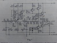
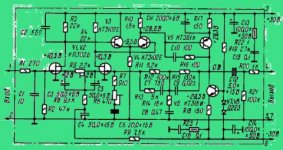
The preamplifier is built after the pattern of an OA equipped with FETs at the input in a differential mode. The stage mixes or combines the advantages of the BJT (regard frequency and high amplification) with the low noise of the P-channel FETs.
Regarding to the type of cardridge, C1 can vary between 10-90pF.
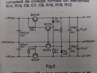
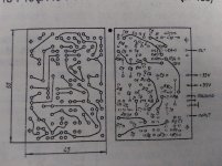
Here are the diagram, the power supply, the part list and the PCB 45 x 55mm
Short description:
"The preamplifier for the magnetic cartridge presented can satisfy a series of lately wishes such as:
-very good signal/noise raport thanks to using the FETs;
-very low THD for a high gain and a high output voltage;
-high capacitance for preloading the signal peaks.
Technical characteristics:
-Gain at 1KHz = 40dB;
-V out = 250mV;
-S/N = 82dB;
-overload for the normal output voltage (250mV) = 40dB;
-THD = 0,01%;
-Z in = 220K;
-minimum Z out = 1K.
The preamplifier is built after the pattern of an OA equipped with FETs at the input in a differential mode. The stage mixes or combines the advantages of the BJT (regard frequency and high amplification) with the low noise of the P-channel FETs.
Regarding to the type of cardridge, C1 can vary between 10-90pF.
Here are the diagram, the power supply, the part list and the PCB 45 x 55mm
Attachments
Last edited:
looks quite good for a single stage RIAA.
T1 & T6 are Nchannel jFETs.
How does it manage +40dB overload capability for 250mV signal with supply rails set to ±33Vdc?
Does the output filter restore the high frequency roll off?
T1 & T6 are Nchannel jFETs.
How does it manage +40dB overload capability for 250mV signal with supply rails set to ±33Vdc?
Does the output filter restore the high frequency roll off?
Last edited:
I like the power supply regulator. May have to borrow that...
The main circuit is yea 'ole standard FET-input discrete opamp with all the fixins. The high number of compensation elements (C2,3,4 & 9) suggests the practical circuit might be a tough one to tame.
The main circuit is yea 'ole standard FET-input discrete opamp with all the fixins. The high number of compensation elements (C2,3,4 & 9) suggests the practical circuit might be a tough one to tame.
The main circuit is yea 'ole standard FET-input discrete opamp with all the fixins. The high number of compensation elements (C2,3,4 & 9) suggests the practical circuit might be a tough one to tame.
Aren't those components the RIAA network, done in the feedback path? This would explain the relative complexity. 🙂
I like the power supply regulator. May have to borrow that...
Could this supply easily be altered to output +-15V?
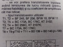
The BD devices appear to be obsolete. Do you know of substitutes?
Thanks...
Looks like a std ckt used by a few japanese mfgs.
there are advantages of dynamic range if you use the +/-30V supplies. lowering the supplies to +/-15V, you may have to adjust some values in the pre-amp ckt.
I think you can change the supply, change the zener diodes to be 15V instead of 33V. may have to lower the zener resistors tro maintain the same current, determined where the zener knee is for the devices you spec. you do not need +/-48V so that can be lowered to save on power dissipation of the pass bjts. Something like no less than +/- 20V should do.
You can use almost any power transistors, usually one uses a to-220 packaged device. you have to determine the supply current, know the un-regulated supply voltage, determine pass bjt Pd and then figure on a heatsink.
Thanks rsavas.
I wasn't going to use it for the phono amplifier listed. I was wanting to power a simple op-amp based line stage with it.
There are probably better options out there. I was looking for something simple, but effective.
I wasn't going to use it for the phono amplifier listed. I was wanting to power a simple op-amp based line stage with it.
There are probably better options out there. I was looking for something simple, but effective.
The supply regulator looks interesting (the preamp not so very) There may be a resistor value typo. I'm thinking of running some sims and posting what may be an improved version when I can get to it. My main computer is down, so I can only play with PSpice when I'm at the job...
Posted with a puny netbook running Linux, with a big monitor hooked up so I can see what the #$@@@&*! I'm doing.
Posted with a puny netbook running Linux, with a big monitor hooked up so I can see what the #$@@@&*! I'm doing.
Looking at the regulator schematic in post #1, the resistors ins series with the zener diodes should both be 3k3. This biases the zener diodes at ~10ma, an appropriate value for a 1W zener that gets the bias off the "knee" and into a region of optimal incremental impedance. A 33k resistor sets the bias for the zener at ~1mA - way too low. The 510R resistors at the collectors of the BC176 and BC256 set their bias currents at a little over 1 mA.
I will try running this regulator in PSpice with available components and see how it fares for transient response and output impedance vs. frequency. I propose replacing the BD237 and BD238 with mosfets, as well as a few changes to speed up the loop and reduce the noise contribution from the zener diodes. I'll post the modified circuit when I can get the simulations done.
I will try running this regulator in PSpice with available components and see how it fares for transient response and output impedance vs. frequency. I propose replacing the BD237 and BD238 with mosfets, as well as a few changes to speed up the loop and reduce the noise contribution from the zener diodes. I'll post the modified circuit when I can get the simulations done.
Last edited:
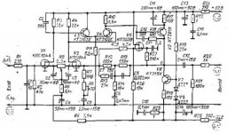
Maybe there is a mistake. I will also upload anothers similar diagrams found on russian websites.
http://ttontw.appspot.com/shema-usilitelya-orfyay.html
http://nauchebe.net/2010/05/usilitel-dlya-magnitodinamicheskoj-golovki-zvukosnimatelya/
http://ttontw.appspot.com/shema-usilitelya-orfyay.html
http://nauchebe.net/2010/05/usilitel-dlya-magnitodinamicheskoj-golovki-zvukosnimatelya/
Attachments
Last edited:
Simulation is useful - the regulator as shown doesn't come up reliably and needs another pair of starting resistors to make things happen. Clue - it's hard to rely on the outputs to drive the pass elements when there's no output, like at startup...
Have a look to the russian diagrams. They are similar with less components at about the same voltage +/- 30....32V.
For the power supply I think that a better rejection could be done using LM317 and its pair LM337.
For the power supply I think that a better rejection could be done using LM317 and its pair LM337.
Interesting is that I found the first diagram presented by me on a russian site with their transistors. Have a look http://radiokot.ru/forum/viewtopic.php?f=42&t=77750&start=80
Attachments
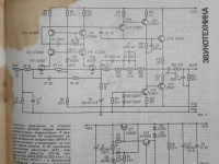
It would be nice to see all of the regulator. It looks like the Russian schematic also addresses the startup issue, but I'd like to see the rest of the regulator to figure out what is going on.
BTW, I have a Nikko Beta preamp with a similar circuit in the phono stage. I'll have to dig it out and compare. The Nikko got bested by some simple single-ended solutions long, long ago. There were some nice circuits in some places but a fair number of corners cut elsewhere.
BTW, I have a Nikko Beta preamp with a similar circuit in the phono stage. I'll have to dig it out and compare. The Nikko got bested by some simple single-ended solutions long, long ago. There were some nice circuits in some places but a fair number of corners cut elsewhere.
Last edited:
I also wondered to see the entire regulator but unfortunately it's not... Maybe only in the original magazine if we can find on the internet we could see it.
I have recommened that Zeners should run at a minimum current that dissipates at least 5% of max dissipation to ensure the dynamic impedance slope is above the knee in the Zener characteristic................This biases the zener diodes at ~10ma, an appropriate value for a 1W zener that gets the bias off the "knee" and into a region of optimal incremental impedance. A 33k resistor sets the bias for the zener at ~1mA - way too low. ..................
But last year some knowledgable Member came back and said that is not the way Zeners work. They work down to very low currents and still stay above the knee.
I have not followed up with any more research to find out which is more true.
I have recommened that Zeners should run at a minimum current that dissipates at least 5% of max dissipation to ensure the dynamic impedance slope is above the knee in the Zener characteristic.
But last year some knowledgable Member came back and said that is not the way Zeners work. They work down to very low currents and still stay above the knee.
I have not followed up with any more research to find out which is more true.
It depends on the zener voltage. Low voltage zeners have a very sloppy knee, so it takes a lot of current to get past it into a useful/stable operating region, in the sense that the voltage drop does not vary dramatically as a function of zener current. Higher voltage zeners, as in this case, have a sharper knee. so it takes less current to get them to the region of relatively flat voltage vs. current. This is reflected in the data sheets, which show reduced test current for higher voltage zeners (though there are considerations also of power dissipation).
To be safe, I would run at least at the specified zener test current from the data sheet. This presumably will get you to the specified value of incremental impedance. Also, starved zeners can be noisy. I found out the hard way...
The supply regulator looks interesting (the preamp not so very) There may be a resistor value typo. I'm thinking of running some sims and posting what may be an improved version when I can get to it. My main computer is down, so I can only play with PSpice when I'm at the job...
Posted with a puny netbook running Linux, with a big monitor hooked up so I can see what the #$@@@&*! I'm doing.
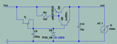
I had tested this DC stabilizer circuit I put together in early November. It measured 55dB PSRR (scope limit) and simulates at 27mOhm Zo wideband flat. It was stable on the breadboard with those transistors and 100 Ohm. I think its related simple topology, if any helpful to you.
Attachments

- Status
- Not open for further replies.
- Home
- Source & Line
- Analog Line Level
- Another JFET phono preamplifier