For the last couple of years I've been trying to come up with a loudspeaker design that provides a balance between "spaciousness" and "pinpoint imaging."
I've owned a bunch of speakers over the last 15 years:
1) Gedlee Summas: Incredibly dynamic and smooth, but not as "spacious" as a conventional speaker. This was due to the 90 degree waveguide, I think.
2) Vandersteen 2CEs: spacious but not dynamic at all. Basically the opposite of the Summas
3) Bill Waslo Cosynes: Similar in sound to the Summas, soundstage depth and intelligibility were improved I think, but dynamics were limited by the use of small midranges
This isn't a criticism of any of these three speakers, just a reflection that I think I prefer something less "pinpoint" and more "spacious."
I've made a bunch of threads lamenting this for 2+ years now, and I think I may have stumbled on a new type of array, so thought I'd share it here.

I think that the "ideal" array might look a lot like the WMTMW arrays from Perlisten, Dave Smith, John Dunlavy, etc. Basically they provide wide horizontal beamwidth and narrow vertical beamwidth.
I've never built a speaker like those, because the cost and complexity of the passive crossover gives me pause. The crossover on the Snell speaker would probably cost $200 per side these days, if not more.
I've been following Dave Smith's thread on arrays, but I've struggled to come up with a line array that performs well with a single driver. And when I try and use two drivers, the passive crossover gets hideously complex and expensive.
I came up with something new that seems to work much better than I could imagine...
I've owned a bunch of speakers over the last 15 years:
1) Gedlee Summas: Incredibly dynamic and smooth, but not as "spacious" as a conventional speaker. This was due to the 90 degree waveguide, I think.
2) Vandersteen 2CEs: spacious but not dynamic at all. Basically the opposite of the Summas
3) Bill Waslo Cosynes: Similar in sound to the Summas, soundstage depth and intelligibility were improved I think, but dynamics were limited by the use of small midranges
This isn't a criticism of any of these three speakers, just a reflection that I think I prefer something less "pinpoint" and more "spacious."
I've made a bunch of threads lamenting this for 2+ years now, and I think I may have stumbled on a new type of array, so thought I'd share it here.
I think that the "ideal" array might look a lot like the WMTMW arrays from Perlisten, Dave Smith, John Dunlavy, etc. Basically they provide wide horizontal beamwidth and narrow vertical beamwidth.
I've never built a speaker like those, because the cost and complexity of the passive crossover gives me pause. The crossover on the Snell speaker would probably cost $200 per side these days, if not more.
I've been following Dave Smith's thread on arrays, but I've struggled to come up with a line array that performs well with a single driver. And when I try and use two drivers, the passive crossover gets hideously complex and expensive.
I came up with something new that seems to work much better than I could imagine...
As documented by Dave Smith, you can improve the beamwidth of a line array by tapering the power that goes to the drivers.
Here's Smith's thread: https://www.diyaudio.com/community/...heir-behavior-through-simple-modeling.388279/
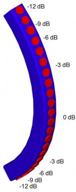
I've attached some pics from the Keele CBT paper, and the CBT works on a similar concept, but the CBT is curved. But the main thing I want to illustrate is that tapering the power keeps the off-axis output from being a mess.
Here's Smith's thread: https://www.diyaudio.com/community/...heir-behavior-through-simple-modeling.388279/
I've attached some pics from the Keele CBT paper, and the CBT works on a similar concept, but the CBT is curved. But the main thing I want to illustrate is that tapering the power keeps the off-axis output from being a mess.
Attachments

OK, this post is really important, and if it doesn't make sense, please ask me.
Because the rest of this thread will make no sense at all if this post doesn't make sense.
Based on years of modeling CBT arrays, I think the reason that "real world" CBT arrays don't perform very well above 5khz is because of:
1) pathlength differences between the various elements
2) Even aggressive power tapering of the array isn't enough to compensate for those pathlength differences
3) Curving the array widens the beamwidth of the array, but makes the high frequency response even worse
In the first pic that I've attached, we see the frequency response of a single driver CBT array. (The "Epique" CBT that Parts Express used to sell.)
You can see the response above 5khz is a mess; the pathlengths are all over the map and vary when you move six inches in the room. Not a big deal for a P.A. speaker that's mostly designed for high output and even coverage, but not great for hifi IMHO
OK so this is the really important part - if you read the latest posts in Dave's line array thread, one way of power tapering an array is so that the size of the array basically gets smaller at high frequency.
1) At 500hz, your array might be 27" tall (one wavelength)
2) At 1000Hz, your array might be 27" tall (one wavelength)
3) At 2000Hz, your array might be 13.5" tall (one wavelength)
4) At 4000hz, your array might be 6.75" tall (one WL)
See post here: https://www.diyaudio.com/community/...r-through-simple-modeling.388279/post-7120303
From the sims that I've been doing, having the height of the array get taller and taller with lower and lower frequencies largely solves the Achilles Heel of the CBT, IMHO. You DO end up discarding a lot of power handling and a lot of efficiency, but when we're talking about a speaker that's over a meter tall, efficiency and power handling aren't much of a concern for a HiFi scenario.
The key to this is that by the time we get to about 2khz or so, only the very center of the array is playing.
But we still have a bunch of issues with this plan, which I'll get to...
Attachments


The concept proposed in post #3 fixes a lot of issues that I have with the CBT array. But it has an Achilles Heel. It's very difficult to filter it passively.
This is for the following reasons:
1) The way to make the array "expand" as frequencies get lower and lower is by having a low pass filter that gets lower and lower as we reach the edges of the array. I've attached pictures of the Keele's CBT array, and what I am proposing is similar. But the difference with what I propose is that the tapering is done with low pass filters, not with resistors. Because the Keele CBT uses resistors, the passive filters can cost as little as $0.25-$1.00 per element. Because what I propose uses low pass filters, if you want to do it passively, you'll need inductors. And inductors can easily cost $10-$20 each these days, due to the high price of copper.
2) You could do the filters with DSP, and that would be a nearly ideal solution. But then you'd be looking at something like twenty four channels of amplification and DSP per side. And TBH, I'm not just opposed to the cost of that, I also don't want a speaker with that level of electronic complexity.
Note that even if you do the filtering passively, you will likely need an electronic high pass filter. This is because the array gets larger and larger as frequencies get lower and lower. So that means the efficiency gets higher. But the high pass filter for this concept is fairly simple, a 2nd order high pass flattens out the response and can be implemented with an $80 MiniDSP. And if the LOW pass filters are done passively, all you need is a single high pass to produce a flat response.
The attached pictures are from the CBT docs, but give you an idea of how the filtering behaves for what I propose. The main difference is that the tapering is done via low pass filters, not resistors. At low frequencies, the array is large, at high frequencies, the array is small.
Attachments

You want to expand the array symmetrically or only in one direction? Symmetrical expansion needs only half of filters if I understand it properly.
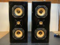
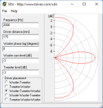
Attached are a few pics of MTM arrays. They were popular in the 90s but went out of style because the output off axis is about as loud as it is ON-axis; this creates a scenario where the sound bouncing off the floor and the ceiling is as loud as what is reaching your ears. This muddies the sound badly and can't be fixed with EQ.
The third pic I've attached shows the vertical polars of an MTM at their crossover point when the spacing is one wavelength.
The fourth pic I've attached shows the vertical polars of an MTM at their crossover point when the spacing is one half wavelength.
You can see from the pics that:
1) reducing the spacing by 50% eliminates the sound hitting the floor and ceiling AND widens the beamwidth on axis
2) or you can lower the xover by one octave and keep the spacing the same
Attachments

So the fundamental challenge with an MTM is that you can't get the woofers close enough together.
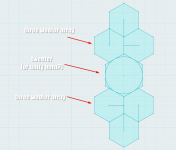
So what I came up with, is something akin to an MTM array, but that the woofers in the array have been replaced with THREE smaller drivers, so that they can be packed together as tightly as possible. Basically using every last millimeter of space possible.
This has quite a few advantages:
1) The center to center spacing of the tweeter and the midbasses is much tighter. This improves just about everything; vertical beamwidth, frequency response at the crossover point, the baffle is smaller and more WAF friendly, etc
2) I think that Mabat has demonstrated quite convincingly that round waveguides can work quite well. I've generally opted for rectangular waveguides, and part of that was aesthetic but part of it was also just following along with what most speaker manufacturers use. But the round waveguides seem legit, and this hexagonal driver arrangement is particularly well suited to them.
3) Three inexpensive woofers can often equal one expensive woofer. A Tymphany TC9 costs about $18 and it can't get nearly as loud as a $51 SB15NRXC30. But THREE TC9s get pretty close to that performance.
4) This array of six drivers simplifies the passive crossover quite a bit. I'll get to that soon...
Attachments

Last edited:
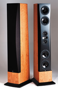
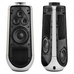
I wasn't trying to copy the Beolab 50 or the Beolab 90, but after I came up with this arrangement, I definitely noticed a resemblance.
I made a thread about the Beolab 90 years ago, and at the time I speculated that the use of three woofers was because B&O was trying to achieve a spherical wavefront.
That may be the case, but now that I've been messing around with hexagonal arrays, the obvious reason to use them is because you can steer the beam vertically.
That's the secret sauce here and it's very cool I think!
Attachments
John> your first post has been my thinking for awhile, and then the Perlisten comes along and really illustrates the ideal with "mid-tweeters". It's the reason I started this thread: https://www.diyaudio.com/community/threads/2-cone-driver-87db-2-83v.387918/, since we can't order custom 1" tweeters that are meant to cross at 1khz.
The tweeter dispersion must be solved though. Now I would use an elliptical waveguide. But when I first prototyped this idea, I was using a Dayton AMT flanked by two Tectonic TEBM46C20N-4B BMRs. I think a slightly taller AMT would be better, but that puts even higher requirements on the mid.

The tweeter dispersion must be solved though. Now I would use an elliptical waveguide. But when I first prototyped this idea, I was using a Dayton AMT flanked by two Tectonic TEBM46C20N-4B BMRs. I think a slightly taller AMT would be better, but that puts even higher requirements on the mid.
3) Three inexpensive woofers can often equal one expensive woofer. A Tymphany TC9 costs about $18 and it can't get nearly as loud as a $51 SB15NRXC30. But THREE TC9s get pretty close to that performance.
I get the choice for the TC9 for a quick prototype build, but to really get the dynamics you're after, wouldn't slightly bigger mids (like the ones in the Beolab) make more sense? 6x a 11 or 12 cm would make the cones move less, ~ 49 cm2 vs 36 cm2... to bad the 12M or MU are that expensive 😉, Peerless HDS-P830870 maybe (56.8 cm2), nice and flat FR? More expensive? Yes. More powerful and/or dynamic? Yes.
Last edited:
Earlier today, I mentioned that hexagonal arrays simplify the passive crossover. Here's why that is.

The shading in most of the CBT speakers is accomplished via resistors. This works, but isn't "ideal" for a few reasons:
1) maximum output and efficiency of the array is compromised, because the elements at the end of the array are getting a fraction of the power that they're rated for.
2) Although it's not a huge issue, the resistors will cause the woofers to have varying Qes. Basically a resistor changes the Qes and the Qts of the alignment. So you end up with an array where the drivers at the edge have significantly higher Qts than the ones in the center: https://www.diyaudio.com/community/threads/increasing-qts-by-series-r-for-ob.146804/
In this hexagonal array, instead of reducing the output of the outer elements, we're increasing the output of the INNER elements by using pairs.
For instance:

If you have two 5" woofers side by side, and each one is receiving the same amount of power, they will behave comparably to an oval shaped woofer that's 3dB more efficient. If you wire the voice coils in parallel, the two BOTTOM woofers in the pair of three woofers will behave like an oval shaped woofer that's radiating 6dB more output than the ROUND one above it.
I know that sounds confusing, but it's not as bad as it sounds.
The idea is to basically accomplish the array shading that Keele and Smith recommend, but to do it without using resistor values that are outrageously high, and without throwing away a ton of array efficiency by heating up resistors.
You could also do a little bit of both; for instance you could wire the bottom two woofers in the triad in parallel, getting you +6dB. Then you could knock down the efficiency by 3dB with a resistor. But you wouldn't need a LARGE resistor because the two drivers in parallel will have a low impedance (because they're in parallel.)
If all of this sounds like a lot of work just to avoid using resistors, you should have seen how complex the passive crossover was, until I came up with this solution.
In a nutshell, if you're using resistors to "shade" an array, once you start trying to filter the elements in the array, it just gets RIDICULOUSLY complex. This is because:
1) By far the biggest issue is the rising impedance of the woofers. Putting resistors inline with the woofers means that the impedance curve of nearly every element in the array is significantly different, screwing up your crossover response.
2) The array doesn't function properly if the elements in the array do NOT have a similar response. For instance, if you have six elements in the array and two of them have a 3dB dip in the upper midrange, due to the interaction between inductors and resistors, your polar response becomes a mess.
3) It is possible to curve the wavefront of a loudspeaker array by using higher order filters on the outside of the array. This is really cool; curved arrays are ugly and difficult to build. You can curve the wavefront in the crossover... but ONLY if the impedance curve is well behaved.
4) The obvious solution here is to use a zobel network to flatten the impedance. Go ahead and open your checkbook for this one, if you go this route it's pretty easy to spend $1000 on the passive crossover. Plus imagine the complexity of wiring that. One wrong connection and you'll be pulling your hair out trying to fix it.
In a nutshell, I think that using a PAIR of drivers, side by side, is an elegant solution here.
One thing to note: keep in mind that using a side-by-side pair is going to limit how high they can play. But we have a fair amount of leeway; a pair of 5" woofers side by side basically act like an oval that's about 9" wide, so beaming won't even start until 1500Hz. I can live with that.
The shading in most of the CBT speakers is accomplished via resistors. This works, but isn't "ideal" for a few reasons:
1) maximum output and efficiency of the array is compromised, because the elements at the end of the array are getting a fraction of the power that they're rated for.
2) Although it's not a huge issue, the resistors will cause the woofers to have varying Qes. Basically a resistor changes the Qes and the Qts of the alignment. So you end up with an array where the drivers at the edge have significantly higher Qts than the ones in the center: https://www.diyaudio.com/community/threads/increasing-qts-by-series-r-for-ob.146804/
In this hexagonal array, instead of reducing the output of the outer elements, we're increasing the output of the INNER elements by using pairs.
For instance:
If you have two 5" woofers side by side, and each one is receiving the same amount of power, they will behave comparably to an oval shaped woofer that's 3dB more efficient. If you wire the voice coils in parallel, the two BOTTOM woofers in the pair of three woofers will behave like an oval shaped woofer that's radiating 6dB more output than the ROUND one above it.
I know that sounds confusing, but it's not as bad as it sounds.
The idea is to basically accomplish the array shading that Keele and Smith recommend, but to do it without using resistor values that are outrageously high, and without throwing away a ton of array efficiency by heating up resistors.
You could also do a little bit of both; for instance you could wire the bottom two woofers in the triad in parallel, getting you +6dB. Then you could knock down the efficiency by 3dB with a resistor. But you wouldn't need a LARGE resistor because the two drivers in parallel will have a low impedance (because they're in parallel.)
If all of this sounds like a lot of work just to avoid using resistors, you should have seen how complex the passive crossover was, until I came up with this solution.
In a nutshell, if you're using resistors to "shade" an array, once you start trying to filter the elements in the array, it just gets RIDICULOUSLY complex. This is because:
1) By far the biggest issue is the rising impedance of the woofers. Putting resistors inline with the woofers means that the impedance curve of nearly every element in the array is significantly different, screwing up your crossover response.
2) The array doesn't function properly if the elements in the array do NOT have a similar response. For instance, if you have six elements in the array and two of them have a 3dB dip in the upper midrange, due to the interaction between inductors and resistors, your polar response becomes a mess.
3) It is possible to curve the wavefront of a loudspeaker array by using higher order filters on the outside of the array. This is really cool; curved arrays are ugly and difficult to build. You can curve the wavefront in the crossover... but ONLY if the impedance curve is well behaved.
4) The obvious solution here is to use a zobel network to flatten the impedance. Go ahead and open your checkbook for this one, if you go this route it's pretty easy to spend $1000 on the passive crossover. Plus imagine the complexity of wiring that. One wrong connection and you'll be pulling your hair out trying to fix it.
In a nutshell, I think that using a PAIR of drivers, side by side, is an elegant solution here.
One thing to note: keep in mind that using a side-by-side pair is going to limit how high they can play. But we have a fair amount of leeway; a pair of 5" woofers side by side basically act like an oval that's about 9" wide, so beaming won't even start until 1500Hz. I can live with that.
Attachments
I'm not sure an array of small drivers will meet the objective. Two 2" drivers will have worse dispersion than one 5". So each array would already be quite "beamy". This is just off the top of my head, you'd really need to model it to know for sure. I know I had to get those Tectonics very close to get a reasonably smooth ceiling/floor bounce when the crossover was 3.5khz.
I get the choice for the TC9 for a quick prototype build, but to really get the dynamics you're after, wouldn't slightly bigger mids (like the ones in the Beolab) make more sense? 6x a 11 or 12 cm would make the cones move less, ~ 49 cm2 vs 36 cm2... to bad the 12M or MU are that expensive 😉, Peerless HDS-P830870 maybe (56.8 cm2), nice and flat FR? More expensive? Yes. More powerful and/or dynamic? Yes.
I'll get to this in a minute, but I think the "trick" here is that you can Go Fractal with a hexagonal array.
You could use three five inch drivers in a triad. That gets you a power handling of about 150 watts and an efficiency of about 90dB with one watt. So you can hit over 110dB, and if you do an MTM you can get that over 115dB. So definitely "dynamic."
But you can also use smaller drivers and take advantage of a plethora of voice coils.
For instance, four 3" drivers with three 3" drivers nested above it and two more 3" drivers above that and one 3" driver at the top. That's ten 3" drivers in an array that measures about 12" x 12" overall, with ten voice coils. Should be good for about 250 watts, or about as much as you'd get from a good 12" midrange. But the "bonus" is that you can shade the array to change the beamwidth.
Or just do what B&O did with the Beolab 50. Basically the really critical parts of the array are what's close to the tweeter. Since it's an expanding array, it's the region near the center where the wavelengths are really short and we need to pack as many small drivers close to the tweeter as possible.
I'm not sure an array of small drivers will meet the objective. Two 2" drivers will have worse dispersion than one 5". So each array would already be quite "beamy". This is just off the top of my head, you'd really need to model it to know for sure. I know I had to get those Tectonics very close to get a reasonably smooth ceiling/floor bounce when the crossover was 3.5khz.
Oh the sims will blow your mind, believe me 🙂
I suppose you are crossing the waveguide quite low? I could see that meshing well with the small driver arrays.
A couple things, you keep menitoning the size of the array. If you use an MTM that is crossed over low, say ~450 hz with a device like the B&C ME464 horn and a capable 1.4" driver like the BMS 4594HE or B&C DCX464, how large is the size of the array above the crossover point?😉
You guys are one step ahead of me. The crossover point is indeed low.
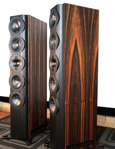
This is far from the final version of things, if I can carve out some time over the weekend I'd like to reduce the size of the midranges and the waveguide. In this current iteration, it has:
a seven inch waveguide
flanked by six five inch woofers

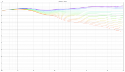
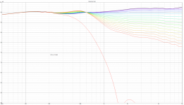
Here's the vertical polars. Can you believe these? When I first saw these I was floored. These are not normalized!!!


Here's the horizontal polars. Note that the horizontal directivity collapses about 700Hz. Waveguide is seven inches in diameter; the reason it goes so low is because of the roundover. Waveguide is a scaled down version of Mabat's CE360: https://www.diyaudio.com/community/...-design-the-easy-way-ath4.338806/post-6752296
In the attached impedance graph, you can see it's not too bad, dipping down to 4ohm. The six woofers are wired series parallel and the inductors in the crossover raise the impedance about one ohm.
There's a spurious line in the horizontal polars, that seems to be some artifact from importing the data into Vituixcad from the output of ABEC
The crossover is the same crossover I generally use with Unity horns:
https://www.diymobileaudio.com/threads/crossovers-a-step-further.163839/page-6
https://www.google.com/search?q=crossovers+a+step+further
Part of the reason that the polar response is crazy good, is because the Lecleach crossover adds a passive delay via the combination of setting the tweeter backwards, flipping the polarity, and then compensating for all of that via the slope of the passive filter. The Lecleach crossover is basically a clever way of using high order slopes but achieves a phase response that's nearly as good as a first order filter. You can scale it up or down as you'd like, the "main" part of the secret sauce is basically trading "depth of tweeter" with "crossover order." The higher the slope on the crossover, the more you need to recess the tweeter, and vice versa.
This is far from the final version of things, if I can carve out some time over the weekend I'd like to reduce the size of the midranges and the waveguide. In this current iteration, it has:
a seven inch waveguide
flanked by six five inch woofers
Here's the vertical polars. Can you believe these? When I first saw these I was floored. These are not normalized!!!
Here's the horizontal polars. Note that the horizontal directivity collapses about 700Hz. Waveguide is seven inches in diameter; the reason it goes so low is because of the roundover. Waveguide is a scaled down version of Mabat's CE360: https://www.diyaudio.com/community/...-design-the-easy-way-ath4.338806/post-6752296
In the attached impedance graph, you can see it's not too bad, dipping down to 4ohm. The six woofers are wired series parallel and the inductors in the crossover raise the impedance about one ohm.
There's a spurious line in the horizontal polars, that seems to be some artifact from importing the data into Vituixcad from the output of ABEC
The crossover is the same crossover I generally use with Unity horns:
https://www.diymobileaudio.com/threads/crossovers-a-step-further.163839/page-6
https://www.google.com/search?q=crossovers+a+step+further
Part of the reason that the polar response is crazy good, is because the Lecleach crossover adds a passive delay via the combination of setting the tweeter backwards, flipping the polarity, and then compensating for all of that via the slope of the passive filter. The Lecleach crossover is basically a clever way of using high order slopes but achieves a phase response that's nearly as good as a first order filter. You can scale it up or down as you'd like, the "main" part of the secret sauce is basically trading "depth of tweeter" with "crossover order." The higher the slope on the crossover, the more you need to recess the tweeter, and vice versa.
Attachments
-
 2022-09-24 12_35_16-VituixCAD_ C__Users_johnv_Documents_VituixCAD_Projects_straight 6 sep18 20...png50 KB · Views: 699
 -
 2022-09-24 12_40_24-VituixCAD_ C__Users_johnv_Documents_VituixCAD_Projects_straight 6 sep18 20...png37.6 KB · Views: 98
 -
 2022-09-24 13_06_17-VituixCAD_ C__Users_johnv_Documents_VituixCAD_Projects_straight 6 sep18 20...png46.7 KB · Views: 98
Last edited:

Here's the crossover, and an animation illustrating what the additional woofers are doing.
Basically, the low pass xover is a simple third order crossover. Nothing fancy, no resistors needed to to shade the array. The two drivers closest to the waveguide behave like one oval shaped driver that's 6dB louder than the round driver above it.
Because they behave like a single oval driver, that might be a problem, but it's not. Because they're only operating below 500Hz and 500hz is twenty seven inches long.
In many respects, the only function for the top and bottom driver is to just extend how low the entire speaker has beamwidth control; they're there to lengthen the array.
The weird vertical arrangement of the crossover in vituixcad is purely because I haven't figured out how to rearrange the windows in the software. (Is that possible?)
There's an active highpass on the tweeter element, and in the real world that tweeter element would likely be replaced with a Unity horn. It's a tight fit, but you can fit one tweeter and four midranges onto a Unity horn that's seven inches in diameter. Another possibility would be using a compression driver with a 1.4" throat, but I personally prefer Unity horns. YMMV
The only reason that the "active gain" device is inline with the tweeter, in the xover, is because ABEC outputs it's FRD files starting at zero dB. IE, I needed to increase the levels in the FRD file, and I was too lazy to write a bash script to do it. Plus, there's 38 FRD files.
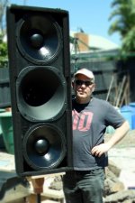
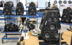
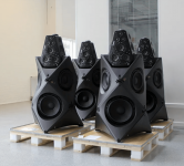
Something else you might want to consider is a "ring array".
 .
.
I've had these in our bedroom closet for over 5 years, awaiting new electronics. I was using a 6-channel XBox Spherex amp with the DSP inside the Apogee chips for the crossover. However, in order to re-do it better, I need 10 channels with DSP for each side, and I keep putting off that design. But maybe this winter...
I've had these in our bedroom closet for over 5 years, awaiting new electronics. I was using a 6-channel XBox Spherex amp with the DSP inside the Apogee chips for the crossover. However, in order to re-do it better, I need 10 channels with DSP for each side, and I keep putting off that design. But maybe this winter...
Last edited:
- Home
- Loudspeakers
- Multi-Way
- Another Improved Array - Sep 2022