I am looking for opinions as how to best dress the heater wiring for the 866A's I am using. The transformer is a 5V and the tubes will be run in series. Twisting the leads doesn't seem to be beneficial as there still will be long sections of non-twisted wire.
The B+ wire also seems to be problematic as well as the wire connecting the two sockets.
A side question would be, how would you deal with three wires that are carrying AC? Twisting them seem that it would lead to asymmetrical cancellation.

The B+ wire also seems to be problematic as well as the wire connecting the two sockets.
A side question would be, how would you deal with three wires that are carrying AC? Twisting them seem that it would lead to asymmetrical cancellation.
If the 866A's are in series the CT (green/yellow stripe) isn't used, coil it up out of the way. connect the valves as you have it ( but shorter wires) with one end grounded. Is this a PP OP stage? If so you may be ok hum wise, if not you might need a rethink.
Andy.
Andy.
Won't the CT be needed in some way for the +VE from the rectifier?

866 valve museum
Perhaps you need to draw the inteneded circuit to help visualise it? Was the 5V CT 8A transformer specified in the design?
866 valve museum
Perhaps you need to draw the inteneded circuit to help visualise it? Was the 5V CT 8A transformer specified in the design?
Scrub what I said, that's wrong, wasn't thinking. The problem is the schematic shows the 866A filaments connected in parallel, your on about connecting them in series to a 5v tfmr. The 866A filament voltage is 2.5v at 5A, parallel connected as shown it'd require a 2.5v 10A (at least) tfmr with CT. your intending to use a 5v 8A tfmr, connecting the 866A's in series so each sees 2.5v, but they'll still need 10A, 8A not enough.
Each 866A is a halfwave rectifier, so each will conduct on each half of the AC cycle, therefore in theory (I think) your tfmr should work with the CT as B+/HT. One big problem, I'd bet that 5v tfmr isn't insulated for over 1000v continuous. If you decide to go ahead, which is iffy, insulate that tfmr from chassis.
If I was building that, I'd take the 5v tfmr apart, rewind it with thicker gauge wire at the correct voltage but also heavily insulate the primary from the secondary then impregnate with high dialetric varnish. But really you'll need a bigger tfmr or more laminations.
Folks with more experience than myself will hopefully chip in with advice. Andy.
The transformer was NOT specified. I just worked in PSUD to help me with the "design".
.png")
The test voltage of that transformer is 2,000V (Data)
I have a 15A 5V transformer but it is a monster and a trusted source said the series connection would allow me to use the smaller 8A transformer. When I breadboarded the amps I used a 15A transformer and had to burn off a lot of current with 3 x 150Ω 7W resistors to get to 2.5V at the sockets. Clearly I need more research.
Thanks guys.
I am not sure I understand where your problem is. Just twist the green and blue wires in your photo, forming a T. The vertial part of the T is formed by the two green wires. The horizontal part of the T is formed by the blue wire and the two green wires (one on the left, the other on the right).I am looking for opinions as how to best dress the heater wiring for the 866A's I am using. The transformer is a 5V and the tubes will be run in series. Twisting the leads doesn't seem to be beneficial as there still will be long sections of non-twisted wire.
Good suggestion! What then should I do with the CT wire that carries the B+?I am not sure I understand where your problem is. Just twist the green and blue wires in your photo, forming a T. The vertial part of the T is formed by the two green wires. The horizontal part of the T is formed by the blue wire and the two green wires (one on the left, the other on the right).
B+ goes separate from the heaters. The idea of twisting the heater wires is that the electromagnetic fields created by the current flowing through the heater wires are cancelled as much as possible (currents flowing in opposite directions, with minimal loop area). The B+ wire is not part of this heater current loop, so it should not be twisted with the heater wires.
Well I set up a test jig and measured the amp draw. Interestingly, I measured only 4.4A with just the heaters running.Scrub what I said, that's wrong, wasn't thinking. The problem is the schematic shows the 866A filaments connected in parallel, your on about connecting them in series to a 5v tfmr. The 866A filament voltage is 2.5v at 5A, parallel connected as shown it'd require a 2.5v 10A (at least) tfmr with CT. your intending to use a 5v 8A tfmr, connecting the 866A's in series so each sees 2.5v, but they'll still need 10A, 8A not enough.
Each 866A is a halfwave rectifier, so each will conduct on each half of the AC cycle, therefore in theory (I think) your tfmr should work with the CT as B+/HT. One big problem, I'd bet that 5v tfmr isn't insulated for over 1000v continuous. If you decide to go ahead, which is iffy, insulate that tfmr from chassis.
If I was building that, I'd take the 5v tfmr apart, rewind it with thicker gauge wire at the correct voltage but also heavily insulate the primary from the secondary then impregnate with high dialetric varnish. But really you'll need a bigger tfmr or more laminations.
Folks with more experience than myself will hopefully chip in with advice. Andy.
Odd. 12AX7's,12AU7's etc have the ability to be wired in parallel and series - 6.3v @ 0.3A, 12.6v @ 0.15A,so, double the voltage half the current. In your case though each 866A shares the voltage (5v) and should "see" or have 2.5v across each one. Because the voltage isn't double effectively then current draw should be the same for each, IE 5A as specified on the datasheet. Might be an idea to measure the voltage across each 866A.Well I set up a test jig and measured the amp draw. Interestingly, I measured only 4.4A
A potential problem of running valve heaters in series that aren't meant to be connected in series is that voltage and current may not be equal for each. One possibilty is that if they haven't been powered up for a long time then they may not be drawing full current. Mercury rectifiers should be heated for about 20-30 minutes before applying AC if they haven't been powered up for a long time. Or possibly because they aren't loaded they may not be drawing full filament current. I have a few 866A's, I'll dig them out tomorrow and power them up and see what I get.
Andy.
Last edited:
That would be very cool and much appreciated!!!Odd. 12AX7's,12AU7's etc have the ability to be wired in parallel and series - 6.3v @ 0.3A, 12.6v @ 0.15A,so, double the voltage half the current. In your case though each 866A shares the voltage (5v) and should "see" or have 2.5v across each one. Because the voltage isn't double effectively then current draw should be the same for each, IE 5A as specified on the datasheet. Might be an idea to measure the voltage across each 866A.
A potential problem of running valve heaters in series that aren't meant to be connected in series is that voltage and current may not be equal for each. One possibilty is that if they haven't been powered up for a long time then they may not be drawing full current. Mercury rectifiers should be heated for about 20-30 minutes before applying AC if they haven't been powered up for a long time. Or possibly because they aren't loaded they may not be drawing full filament current. I have a few 866A's, I'll dig them out tomorrow and power them up and see what I get.
Andy.
Yes, but we do not take output power from the heaters/filaments.12AX7's,12AU7's etc have the ability to be wired in parallel and series
My gut says the 5VCT 8A winding can stand both tubes on one side. That side is 25% overloaded but the other side is no-load, the transformer won't burn up. However now we have to take B+ output from one end of the winding, which throws non-negligible 60Hz in the DC.
I think that's not the best transformer but I understand about global shortages this year.
But I'm using both sides of the transformer as shown. Drawing my B+ from the center tap.Yes, but we do not take output power from the heaters/filaments.
My gut says the 5VCT 8A winding can stand both tubes on one side. That side is 25% overloaded but the other side is no-load, the transformer won't burn up. However now we have to take B+ output from one end of the winding, which throws non-negligible 60Hz in the DC.
I think that's not the best transformer but I understand about global shortages this year.
Attachments
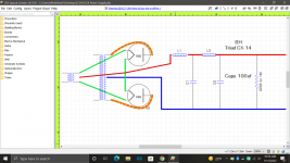
Wouldn't it be better to use each half of the secondary for each rectifier, taking the CT to each tube, so that there is no potential issue about the balancing of the heater supplies. It looks like they do need their 2.5V to be exact
My latest amp runs the heaters in series and gets the B+ from one side of the filament transformer. No center tap.
I don't know. I'm a novice and this was working on the breadboard for a couple of months.Wouldn't it be better to use each half of the secondary for each rectifier, taking the CT to each tube, so that there is no potential issue about the balancing of the heater supplies. It looks like they do need their 2.5V to be exact
My building partner and I built a HV supply using "vintage" (been on the shelf for decades, free) parts a couple years ago:
https://www.itishifi.com/archives//2019/08/monolithic-tube-power-supply-success.html
We also used a (beautiful Bendix mil-surp) 5.0 VAC-CT filament transformer, with B+ taken from the center tap. Some issues that need to be considered with 866's:
The 866's need to warm up for half a minute to a minute before plate voltage is applied. No, you cannot cheat on this.
All of the power supply chokes are of trivial current limiting importance during intial turn-on charging of the power supply capacitors - they're too small to matter at cap charging rate. So, you'll need to also include some current ramp-up limiting. Indirectly heated damper diodes work fine.
Voltages on the hot side of the first choke are in multiple kiloVolts. Everything needs to be rated for 5000 Volts, including all standoffs, transformer windings, etc. DO NOT try to insulate transformers from chassis - that's dangerously nuts.
Not to be discouraging, but safety and reliability issues with 866's are not trivial. Also, don't stare at them; even later 866A models with internal shields still make a lot of UV.
All good fortune,
Chris
edit: should mention: common point of 866 filaments should connect to transformer CT = B+.
Last edited:
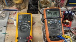
If you've connected the common point of the filaments to the transformer's center tap, you're going to be fine for voltage balance.Here are the readings with both tubes in series. Are they close enough to live with or should I source a 2.5V@10A transformer?
Is there a good reason to spend another $60.00USD to run them in parallel?
But, looking harder at the picture in the first post, am I seeing insulators standing the power supply chokes off from chassis? Is there a separate safety wire from their frames to chassis? If not, you MUST do this. Otherwise you'll have the easy potential of a fatal charge between choke frame and chassis.
All good fortune, and please be safe,
Chris
- Home
- Amplifiers
- Tubes / Valves
- Another Heater Wiring Question