tinitus - Very interesting. How did you determine that the size and shape of the magnetic field had been changed by the copper strip? Are you measuring or simulating?
Denis
I use the tip of a very small screw driver 😀 amasing how much it can tell you 🙂
Its clear to me that the field in front of magnets gets flatter with the copper
It also bends down closer to the edge
In other words, it gets more concentrated
one other advantage of this design is that it makes use of wide and very strong magnets possible, without affecting the gap size
my magnets are too small and should be twice as big
mine may pull about 10pounds, and twice the size pulls something like 50pounds
another issue that might be worth to consider is the size of the magnet surface having contact with the iron
it might matter, but I dont know about that
Attachments
I'm hesitating about the gap between between the magnets.. as you can see in the pictures I'm trying to move them together. Anyway, they seem to work fine.
http://dsl.mine.nu/galleri/misc/band1.jpg
http://dsl.mine.nu/band.jpg
http://dsl.mine.nu/galleri/misc/band1.jpg
http://dsl.mine.nu/band.jpg
I use the tip of a very small screw driver 😀 amasing how much it can tell you 🙂
Its clear to me that the field in front of magnets gets flatter with the copper
It also bends down closer to the edge
In other words, it gets more concentrated
...
Hello Tinitus,
copper is diamagnetic, which means μrel <1.
Permeability (electromagnetism) - Wikipedia, the free encyclopedia
But a value of 0.999994 for copper compared to 1.00000037 for air seems unlikely to have
noticeable influence on the design of the magnetic circuit itself.
You should get a hall probe for measurements, i fear the effect might boil down
to "wishful thinking".
Holding the screw driver in a very slightly different angle, should have
by far more influence on the forces you experience than the copper being
in the gap or not.
To measure the forces that way you would need a precision robot handling
the screw driver and very sensitive force sensors ...
No job for a human being, as i see it.
Or is there something i am overlooking (any of the physicists in here) ?
Maybe cooling the copper down using liquid helium might help to make
it superconducting with μrel =0 ?
Kind Regards
Last edited:
I made ribbon tweeter on the basis of hard drive magnets.hard drive magnets - bad!
I complemented it with 10” woofer and got the such speaker system.
Сrossover frequency: 1 kHz / 2nd-Order.
Also I improved ecological state of the planet: I devised the method of second using wastes of electronic components – HDD.
Interesting work, could you tell us more about the construction of the tweeter?
I have several Hd magnet waiting for a new life...
I have several Hd magnet waiting for a new life...
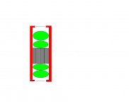
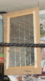
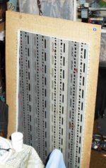
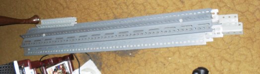
I take a sheet of iron 1.5 mm thick and cut rectangles 2.5sm width. Each tweeter needs 3 such rectangles-guides. Magnets are glued on guides. Clothespins help to fix magnets during gluing.

I cut a piece of 9-ply plywood. This the piece is basis for the magnetic system.


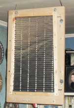
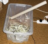
In these tweeters I used ribbon from the condenser, it is thinner than the food foil.

There is a machine for corrugating of ribbon on the photo.

I make two ribbon with different thicknesses and step of corrugating.

Mandatory installation of grid

I cut a piece of 9-ply plywood. This the piece is basis for the magnetic system.
In these tweeters I used ribbon from the condenser, it is thinner than the food foil.
There is a machine for corrugating of ribbon on the photo.
I make two ribbon with different thicknesses and step of corrugating.
Mandatory installation of grid
Ingenious ... did you use a DIY transformer to adapt the impedance?
Why did you use the grill?
How does it sound?
Why did you use the grill?
How does it sound?
I set grill for two my little kids, because they like to poke fingers anywhere.
I like my corrugating machine too. It’s the absurd thing, but useful.
You can assess quality of sound on the video.
First link – dynamic camera:??????.?????
Second link – static camera:??????.?????
distance to speaker system 2,5m
I like my corrugating machine too. It’s the absurd thing, but useful.
You can assess quality of sound on the video.
First link – dynamic camera:??????.?????
Second link – static camera:??????.?????
distance to speaker system 2,5m
Thank you kyne4ik, I figure the reason why you put the grill at the same time I figure a ribbon in my house .
" It’s the absurd thing, but useful" I think it's an intelligent use of everyday stuff, but useful :-D
" It’s the absurd thing, but useful" I think it's an intelligent use of everyday stuff, but useful :-D
Here is something different , still ribbon.
http://www.faktiskt.se/modules.php?name=Forums&file=viewtopic&t=41909
Bernt
http://www.faktiskt.se/modules.php?name=Forums&file=viewtopic&t=41909
Bernt
They sound really awesome, no one believe when see the ribbon moving, im with problem some problems ($$) on project of ribbon supports, a guy said that will cost arround 80USD to make 4 teflon supports for the aluminium ribbon, im thinking now on some cheaper material, later i can put a gold coated pcb to act as ribbon contacts.
How this will be a wide range speaker (arround 300~20khz) im with some doubts on back filling of speaker, with no filling thats to much distortion from the chamber, i tried with 25mm 33D density foam and got a good result, i thinking on make 3 o 4 damping layers: 33d foam, glass fiber and cotton all to prevent any refraction and distortion from back walls. This is the problem on use non dipole ribbon tweeter 🙁
About the weigh, only ribbons are arround 30 kg each, the cabinets idk yet, but with the amount of mdf used on they i can say arround 80 kg each, aaaah i forgot... more 10kg of 6" midbass!
Murilo
Can't You just cut slices out of the back chamber to let the air out?
You would still have a magnetic circuit that way.
Like Magnepans ribbon tweeter.

Otherwise You will have to calculate the gap-chambers acoustical impedance factor. You will in affect have a Helmholz resonator and thus a monopole ribbon.
Cheers from Sweden!
Last edited:
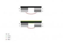
To avoid nasty reflections from all those odd shaped magnets and focus the magnetig field a solution like this could be made.
And it is even dipolar as there are ribbons in front and back.
You can even listen for the difference between monopolar response (disconnect the back ribbon) and dipolar response.
To explain the picture:
Red: Iron
Grey : magnets
Green: damping material
Blue : Ribbons
And it is even dipolar as there are ribbons in front and back.
You can even listen for the difference between monopolar response (disconnect the back ribbon) and dipolar response.
To explain the picture:
Red: Iron
Grey : magnets
Green: damping material
Blue : Ribbons
Attachments
They can be damped out by the damping material.
And I think they are out of the range in witch the ribbon is playing after all. You can make the chamber behind the ribbon appropriatly big, so the problem is far below crossoverpoint, I would guess.
And I think they are out of the range in witch the ribbon is playing after all. You can make the chamber behind the ribbon appropriatly big, so the problem is far below crossoverpoint, I would guess.
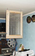
MY LATEST REBUILD.
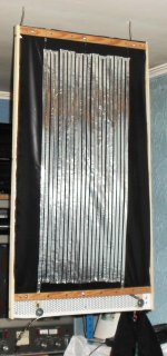
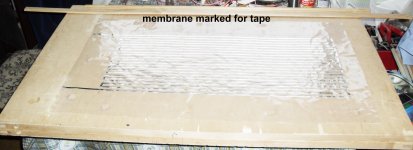
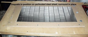
These are my latest rebuilds and I think these are my last designs, famous last words! I have tried various designs over the last 20 years, but since the introduction of neo magnets, this has peeked my interest. I am in the process of rebuilding all my designs using 23 micron Mylar A. I have several pairs to rebuild including ferrite ones. I did use angle iron on these, but I have reduced the weight considerably by not using the angle iron in my upcoming rebuilds. I am very happy with the bass which goes down to 20Hz, and is very tight and focussed. Unlike the bass on the esl 57's and 63's which is quite plummy and resonant.

These are my latest rebuilds and I think these are my last designs, famous last words! I have tried various designs over the last 20 years, but since the introduction of neo magnets, this has peeked my interest. I am in the process of rebuilding all my designs using 23 micron Mylar A. I have several pairs to rebuild including ferrite ones. I did use angle iron on these, but I have reduced the weight considerably by not using the angle iron in my upcoming rebuilds. I am very happy with the bass which goes down to 20Hz, and is very tight and focussed. Unlike the bass on the esl 57's and 63's which is quite plummy and resonant.
Attachments

Some more pictures of my work.
This should help anyone interested in building FRP .No crossovers and down to 20k. I fact I have one of my designs as a sub woofer
This should help anyone interested in building FRP .No crossovers and down to 20k. I fact I have one of my designs as a sub woofer
Attachments
-
 SAM_0548.JPG140.1 KB · Views: 194
 -
 SAM_0543.JPG394.2 KB · Views: 220
 -
 SAM_0523.JPG399.3 KB · Views: 270
 -
 SAM_0561.JPG438.1 KB · Views: 192
 -
 SAM_0575.JPG280.4 KB · Views: 214
 -
 SAM_0584.JPG628.1 KB · Views: 195
 -
 SAM_0585.JPG705.2 KB · Views: 155
 -
 SAM_0586.JPG513.7 KB · Views: 148
 -
 SAM_0587.JPG713.2 KB · Views: 154
 -
 SAM_0588.JPG748.6 KB · Views: 174
- Home
- Loudspeakers
- Planars & Exotics
- Another DIY Ribbon thread