Digging through some notes I had saved I found an article dated November 4, 2010 from EDN Design Ideas.
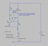
The article covered the basic 2-Transistor current source, changing the pass transistor to a FET, adding a third transistor to form a current source to the control transistor, and finally adding a 6.2V zener to provide temp compensation.
I don't remember seeing this configuration in any of the discussions on current sources so I am posting it.
Simulations look very good except a +2.6dB peak around 850KHz.
Distortion at 20VRMS (4ma) sims at 0.0076%, with rapidly decaying harmonics.
Attachments
- Status
- Not open for further replies.