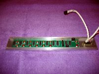
Relay PCB For Preamp
Here is the relay board that inorporates all the switching for the preamp. Dry reed relays are used throughout to eliminate most of the problems associated with mechanical switches. In addition to six input sources, relays are also used for stereo/mono and muting. Another advantage of relays is that expensive dual switches are not required
All the phono connectors are isolated from the chassis by means of fiber washers, and the PCB is separated from the rear panel by shoulder washers which act as standoffs. Getting all the holes in the rear panel to exactly match those in the PCB was a bit of a challenge. I ended up sacrificing one of the PCBs to use as a drill template. If I build more than one preamp I'll use a vertical mill and drill to coordinates.
Attachments
Preamp Completed and Working!
I finished the internal wiring last night and connected the preamp to my stereo. So far I have listened with CD player and phono as input sources. With the phono inputs shorted and volume at max there is no audible hiss or hum. I can already notice a considerable improvement in openness over the preamp it replaced.
When I connect the MC preamp to the phone stage I do get a fair amount of hum. I'll have to track down whether this is due to ground loops or to the MC preamp itself. If it is the latter, I guess I'll have to design and build a new MC preamp. So far I've designed and built power amp and preamp stages, so the MC amp is the logical next step.
Wow! A lot of parts for such a small task.
4 transistors on the input circuit will certainly make that one noisy. Maybe better for a higher output cartridge.
Good luck with that!. Add two more current gain stages and volume control and you have a power amp...
4 transistors on the input circuit will certainly make that one noisy. Maybe better for a higher output cartridge.
Good luck with that!. Add two more current gain stages and volume control and you have a power amp...
Wow! A lot of parts for such a small task
Actually, if you examine opamps implementations, you will see that the number of transistors is not that large.
The preamp is designed to operate with a separate seperate MC preamp. Right now I have an old Vandersteen step-up transformer, although I'm considering designing a transistor-only based replacement. The preamp's equivalent input noise is <1 nv/sqrt(Hz), which is close to what can be obtained from integrated opamp solutions.
I have a simulated paper design for an MC amp which operated in a no-feedback mode, thereby eliminatng the noise associated with the FB network. Using paralleled 2sj74 and 2sk170 JFET models, I get approx 0.3 nV/sqrt(Hz) simulated noise, and distortion is <100 dB. The key to achieving such results lies in a multiple parameter match of the N devices and a similar match for the P devices. In this design N and P devices need not be closely matched. For more details, see my thread on "Matching JFETS".
Simulation versus Actual
This for moving magnet should be quiet enough. For some silly reason thought it was for lower output moving coil.
If you build this I would be extremely interested in the measured results versus what the simulation suggest as for resultant noise and other parameters mentioned. I have had poor luck with the simulators used previously so do not trust them much at all. Maybe the one you use actually works. None of the ones I have tried do.
Please let me know the results if you get the chance.🙂
Schematic problem?
So I looked the design over pretty close and to get useful bias current in the output stage resistors will be required in the emitter of Q5 Q6 to bias Q7 and Q8. Resistor connected directly to emitter Q5 Q6 and other end of resistosr connected to current source and base of Q7 or Q8.
So I looked the design over pretty close and to get useful bias current in the output stage resistors will be required in the emitter of Q5 Q6 to bias Q7 and Q8. Resistor connected directly to emitter Q5 Q6 and other end of resistosr connected to current source and base of Q7 or Q8.
Measurements vs. Simulations
I have had poor luck with the simulators used previously so do not trust them much at all. Maybe the one you use actually works. None of the ones I have tried do.
---------
It should not be too difficult to get noise figures. I can rig up a 20 KHz LPF and insert it between the preamp and an RMS voltmeter. Distortion will be more of a challenge. I can't justify spending over $8K for a distortion analyzer.
I can't prove the simulator I'm using is accurate, although it does yield noise results that are consistent with those advertized by the manufacturer. The simulator I'm using sells for over $100K, but my employer does not mind if I use it for hobby stuff. For that price I would hope it is accurate.
Bias Currents
[QUOTEI looked the design over pretty close and to get useful bias current in the output stage resistors will be required in the emitter of Q5 Q6 to bias Q7 and Q8. Resistor connected directly to emitter Q5 Q6 and other end of resistosr connected to current source and base of Q7 or Q8.[/QUOTE]
I found that the bias current could be controlled sufficiently by setting the current sources appropriately to approx 2.2 ma. I did try larger current values, but there was no appreciable drop in distortion. However, I do understand your argument and will try simulations where emitter resistors are added.
I did design a similar MC preamp, though slightly less complex.
The noise figure quoted, i.e , 0.7 nV/sqrt hz is very realist for
this kind of topology if minimal design guidelines are respected.
i will add that simulations were accurate enough when compared
to real world.
The noise figure quoted, i.e , 0.7 nV/sqrt hz is very realist for
this kind of topology if minimal design guidelines are respected.
i will add that simulations were accurate enough when compared
to real world.
Preamp Noise Measurement
If you build this I would be extremely interested in the measured results versus what the simulationWith the lineamp gain at max (giving an additional 20 dB of gain) the 0-20KHz noise from the phono + line stages is ~400 uVRMS. If I simulate by replacing the actual gain stages with zero noise equivalents (including the RIAA network resistors) and then adjust Rsource, I need 80 ohms to get this amount of noise at the lineamp output. I chose this method because it allows me to account for the RIAA network. 80 ohms is equivalent to an input noise source of 1.15 nV/sqrt(Hz).
Interestingly, when I simulate I get a slightly higher noise level of 1.58 nV/sqrt(Hz). The most likely explanation is the THAT matched transistors have a lower noise characteristic than what's defined in their SPICE models.
It is also clear that for a 170 uV cartridge output, which is what I have, a separate MC amp stage is required. As noted in an earlier thread, I have designed and simulated such an amp with an En of < 0.3 nV/sqrt(Hz). I'll publish details once I have convinced myself that my transistor matching scheme is workable.
I'll publish details once I have convinced myself that my transistor matching scheme is workable.
Analog devices has this:
MAT01: Matched Monolithic Dual Transistor MAT02: Low Noise, Matched Dual Monolithic Transistor MAT02S: Aerospace Low Noise, Matched Dual NPN Transistor MAT03: Low Noise, Matched Dual PNP Transistor MAT03S: Aerospace Low Noise, Matched Dual PNP Transistor MAT04: Matched Monolithic Quad Transistor
MC Pre-preamp
Analog devices has this: MAT01: Matched Monolithic Dual Transistor...
The MC pre-preamp design I am considering utilizes low noise complementary JFETs in a diffamp configuration where the V- input is grounded. My reason for choosing JFETS is the availability of very low noise, complementary devices and the ease of paralleling them to achieve a lower En. This topology also permits a no-GFB configuration that eliminates noise associated with feedback resistances.
I plan to start a new thread for this design.
Sounds good to me. Just thought the matched transistors might be helpful.
I used an LM394 for my moving coil preamp in single ended and measured about .2dB above the theoretical input noise for the device with the cartridge connected. That was a really long time ago. Hope you do better with the FET design. Good luck.
I used an LM394 for my moving coil preamp in single ended and measured about .2dB above the theoretical input noise for the device with the cartridge connected. That was a really long time ago. Hope you do better with the FET design. Good luck.
- Status
- Not open for further replies.
- Home
- Source & Line
- Analogue Source
- Another Discrete BJT MC Preamp Design