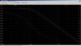
Your crossover frequency is 1/(2*pi()*sqr(C*C*Ra*Rb)). C=10n, Ra=100k, Rb=200k. So I think you can be flexible with the values, in case you need to change the BOM for a reason.
"Should" be 125Hz high and low pass.
Both TL074 and TL084 are JFET input devices.TL074 is JFET-input, quad of TL071 while TL084 is BJT-input, quad of TL81.
TL074 are "low noise" devices, if you can afford 18 nV/sqrt(Hz)

Last edited:
Seriously no reason for looking "HiEnd" components.....mostly BS anyway- but do not use ceramic capacitors for X-over.... normal polyprop like Wima or the likes... should be around 25c in 25-batch...
MLCC C0G NPO caps have very low distortion and are more consistent than film caps.
MLCC C0G NPO caps have very low distortion and are more consistent than film caps.
Are they available in through hole? (yes this is an ancient through hole design although my eyes are not complaining)
So this is what I am coming up with for the .01uf cap:
MKT1817310254 Vishay / Roederstein | Mouser
0.005uf :
184682K630RBA-F Cornell Dubilier - CDE | Mouser
Any objections?
MKT1817310254 Vishay / Roederstein | Mouser
0.005uf :
184682K630RBA-F Cornell Dubilier - CDE | Mouser
Any objections?
Last edited:
Both TL074 and TL084 are JFET input devices.
TL074 are "low noise" devices, if you can afford 18 nV/sqrt(Hz)
Ah! Yes, you're right.
So this is what I am coming up with for the .01uf cap:
MKT1817310254 Vishay / Roederstein | Mouser
0.005uf :
184682K630RBA-F Cornell Dubilier - CDE | Mouser
Any objections?
Will it fit into the PCB? I prefer small ones.
Will it fit into the PCB? I prefer small ones.
According to the BOM (C050-075X040) they should be 7.5mm x 4mm..
According to the spec sheets one is 7.5mm and one is 7.2mm. I "think" I can bend out the leads a little. Am I right or mistaken?
All,
C18 and C19 are listed as .005uf (5000pF) caps.. I am switching to Wima caps and they don't have a .005uf in that physical size.
It's either 4700 or 6800 pF.
Any suggestions on which way I should go?
Since C16 should be twice the C18 (to maintain the proper transfer), there is a useful trick to use any value on C16 and use parallel of the same value on C18. So if C18 is 4.7nF, C16 is 2x 4.7nF (equal 9.4nF). In crossover design this is a neat trick (there are situations you need it) if your parts are small (e.g. SMD or 1/8W resistors, 63V capacitors).
Regarding the better values, I think it is more important to know which crossover frequency is better. If 5nF gives 113Hz then 4n7 will give higher frequency, which IMO is probably what you should want. (Because at 113Hz the initial speaker response might not be that flat)
4700 vs 5000 is 6% or one semi-tone. Very few crossovers need to be that exact. Driver capabilities suggest 400Hz or 600Hz for different goals; I can't think why 500Hz or 532Hz makes the least difference.
However, to be picky: take the cap you can get and then adjust the resistor value. Resistors are available in much narrower bins than capacitors. If, say, 5000p and 100K rings your bell, then 4700p and 106.38K hits the same point. (and 105K is all the same considering your "4700p" may be a few % out.)
However, to be picky: take the cap you can get and then adjust the resistor value. Resistors are available in much narrower bins than capacitors. If, say, 5000p and 100K rings your bell, then 4700p and 106.38K hits the same point. (and 105K is all the same considering your "4700p" may be a few % out.)
- Status
- This old topic is closed. If you want to reopen this topic, contact a moderator using the "Report Post" button.
- Home
- Source & Line
- Analog Line Level
- Another can of worms...