Hi Guys ,
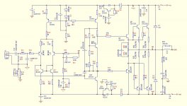
I found this schematic , and have built this. from what i understand this is a blameless topology . it sounds good and transparent , but when i tested this on the scope the sine wave output is perfect from 5hz to 25khz , but square wave gets slightly distorted above 5khz , does that effect the sonic performance of the amp ?
I found this schematic , and have built this. from what i understand this is a blameless topology . it sounds good and transparent , but when i tested this on the scope the sine wave output is perfect from 5hz to 25khz , but square wave gets slightly distorted above 5khz , does that effect the sonic performance of the amp ?
Attachments
Short answer is yes. The slew rate is a little low here. I estimate it as
4.5mA/220pF = 20V/us. That is barely adequate. Also, I think that C value is more than you need to stabilize the amp, but without entering it all into LTspice, I cannot tell you for sure.
You can try incrementally lowering C5 and playing a 1 or 2 V square wave. When you see overshoot and ringing, put the next higher C value back in.
It is wrong to say this is a blameless design. More like "not entirely blameless". Improvements would be emitter follower stage between the input and VAS stages, cascode of the VAS stage, higher beta transistors for the input pair.
The way performance is affected is high THD at higher audio frequencies. The input pair is overworked charging and discharging C5, and becomes non-linear.
What is the benefit of D4, D6? For me they do nothing, just reduce the voltage for the VAS, and input.
Sajti
Sajti
They increase the VAS voltage when it matters, in fact, under heavy load the main rails ripple down a few volts, the diodes prevent these dips getting to the VAS or input section.
Not sure I like them though, when the power goes the VAS can drive the output driver transistors well beyond their rails if the main filter caps are drained fast. I think 4V7 zeners might be safer for this role, so the VAS can never be a much higher voltage than the OS.
Not sure I like them though, when the power goes the VAS can drive the output driver transistors well beyond their rails if the main filter caps are drained fast. I think 4V7 zeners might be safer for this role, so the VAS can never be a much higher voltage than the OS.
They increase the VAS voltage when it matters, in fact, under heavy load the main rails ripple down a few volts, the diodes prevent these dips getting to the VAS or input section.
Yes, if puffer capacitor following them. But there is no capacitor, just ripple eater following the diodes, which is not the optimal solution, i guess...
Sajti
>SlewRate = 20V/us. That is barely adequate
Barely adequate?
Self writes in his book that 20V/us is all 100W amp will ever need.
Clean sinus wave reproduction at 100W only requires 5V/us...
I guess standards went up recently ?
Barely adequate?
Self writes in his book that 20V/us is all 100W amp will ever need.
Clean sinus wave reproduction at 100W only requires 5V/us...
I guess standards went up recently ?
I was under the impression that this was more than a 100 W amplifier. However, I still think 4x headroom on slew rate is only barely adequate. Generally accepted standard, outside of Doug Self is 5x. I really think 10x is the goal.
Current swing on the input pair is very low at low frequencies. As the amp approaches it's slew limit, current in the diff pair approaches its maximum peak-peak current swing. Even at 1/4 the max slew rate, instead of a few uA, the input pair swings from 75% of quiescent to 125% of quiescent. If the input pair is biased at 2 mA each, this is a 1mA peak-peak swing.
The error voltage at the input pair becomes very large. The input pair is forced into non-linear operating regions. This is a large-signal effect not predicted by loop-gain error correction equations. The gain of the input pair is dropping precipitously when this happens. Emitter degeneration helps, but it can only do so much.
Maybe it's not that big a deal, but I and Mr. Self are shooting for THD below 0.001%. These effects start to really matter.
For amps with 0.01% distortion, it's fine to have only 3x or 4x headroom on slew rate.
For amps with 0.01% distortion, it's fine to have only 3x or 4x headroom on slew rate.
Hi Guys ,
I found this schematic , and have built this. from what i understand this is a blameless topology . it sounds good and transparent , but when i tested this on the scope the sine wave output is perfect from 5hz to 25khz , but square wave gets slightly distorted above 5khz , does that effect the sonic performance of the amp ?
Looks like the 18$ Harbinger amp I just built. Russle is right , sloooow.
Most likely it is for a commercial powered speaker/sub application.
The lead/ lag comp. would give 250khz unity gain , 1/5th of some of the (better)
blameless designs. Good sub amp , most likely would not have that crystal
clarity and detail at HF.
OS
- Home
- Amplifiers
- Solid State
- another Blameless Design