I've got one of Frex's AN67 oscillators. It's extremely good stuff. Initially I set it up for 10KHz, but I've since swapped it to 1KHz use. Now of course I want a 10KHz one.
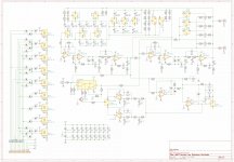
Rather than building many or messing with my existing oscillator, I thought it'd surely be easier to just add some switches to the AN67 schematic so I could change frequency. This is the result of that - frequency selection in 1-2-5 ranges from 10Hz to 10KHz. I've used relays rather than switches because I'm concerned about parasitics, and I think the relays will be a lot cleaner than a switch.
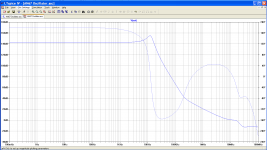
I made a small mod to the AN67 composite amp, by putting a 220K resistor across the 50p cap. This removes the 6dB/octave gain variation, at least out to 1KHz, so we only need the one gain setting for everything up to and including 1KHz. 2KHz, 5KHz and 10KHz get their own trimpots, that are switched in for those frequencies. The mod to the composite amp doesn't appear to have messed with it's stability.
I've also used a pair of integrators, and a pair of low pass filters, which are switchable.
Alas there's no way I can be confident of a simulation or dodgy prototype, due to parasitics, so I think the only way to proceed is to build the real thing.
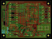
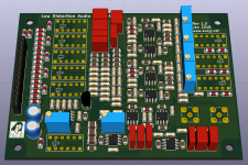
Layout is in KiCAD, a 75x100mm two layer PCB, with 15 thou features and 1206/Mini MELF parts.
Now to order one and do the long wait.
Rather than building many or messing with my existing oscillator, I thought it'd surely be easier to just add some switches to the AN67 schematic so I could change frequency. This is the result of that - frequency selection in 1-2-5 ranges from 10Hz to 10KHz. I've used relays rather than switches because I'm concerned about parasitics, and I think the relays will be a lot cleaner than a switch.
I made a small mod to the AN67 composite amp, by putting a 220K resistor across the 50p cap. This removes the 6dB/octave gain variation, at least out to 1KHz, so we only need the one gain setting for everything up to and including 1KHz. 2KHz, 5KHz and 10KHz get their own trimpots, that are switched in for those frequencies. The mod to the composite amp doesn't appear to have messed with it's stability.
I've also used a pair of integrators, and a pair of low pass filters, which are switchable.
Alas there's no way I can be confident of a simulation or dodgy prototype, due to parasitics, so I think the only way to proceed is to build the real thing.
Layout is in KiCAD, a 75x100mm two layer PCB, with 15 thou features and 1206/Mini MELF parts.
Now to order one and do the long wait.
Attachments
Last edited:
Boards arrived yesterday, and look reasonably good. The logo was a spectacular failure. Alas I don't quite have all the bits to build one - notably I'm out of 240K resistors, plus a few of the larger film caps and trimmers. I've also substituted OP27's for some of the LT1007's in less critical spots, and used the (much) cheaper non-RF version of the G6K relays.
Attachments
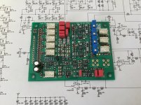
Excellent work. Can't comment on the logo but what is peeking out seems fine.
How close are you to firing this up? Testing it will be a formidable task.
How close are you to firing this up? Testing it will be a formidable task.
Haven't ordered the bits yet - I'm doing some other designs (switched attenuator, notch filter, low noise regulated supply) that are related to this and wanted to order everything together.
Yes, I'm hoping that it'll be a challenge to test. Wouldn't be worthwhile doing if it was easy.
Yes, I'm hoping that it'll be a challenge to test. Wouldn't be worthwhile doing if it was easy.
- Status
- Not open for further replies.