A new Aleph-X has been born.
The baseball card stats for the amplifier are:
Outboard Power Supply
------------------------------
1000VA Plitron transformer for each channel (25VAC dual secondaries)
RCRC filter (0.2 ohms, 2 x 68mF, 0.23 ohms, 68mF - for each rail, 0.4F per amp)
+/- 24 to 26 volts warmed up, 7.5 amps bias
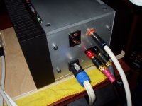
5 wire connection to the amplifier (12 gauge +/return, -/return, earth ground) terminated with Neutrik Speakon connectors, earth ground to amp chassis through thermistor
<100 mV RMS ripple after first cap bank
~10 mV RMS ripple after filtering
28 lbs. each
Amplifier
---------
130W (8 ohms), 190W (4 ohms)
HifiZen boards (a hearty thanks to him for the group buy)
Conrad Heatsinks (151.5 mm tall, 2 x 350 mm long, 1 x 250 mm long)
Vishay/Dale RN60 resistors for low power components
Mills, 5W, non-inductive resistors, for the sense resistors, 1W, 0.47 ohm, 5% metal oxide for current sharing
MOSFETS - IRFP240, 4 sets of 8 (16 per channel), matched to 20 mV Vgs at three different currents, although I may have missed on 2-3, since the current sharing isn't ideal (it could also be the 5% resistors)
input and feedback resistors 0.1% tolerance
all electrolytics on the boards are paralleled with 100nF MKP caps placed underneath the board
3.3k "magic" resistors, 2||62 ohm resistors from the output to ground
32mV and 17mV differential DC offset on the outputs
typically less than 0.5V absolute DC offset when warmed up
23 lbs. each
Pictures and commentary to follow.
Jeremy
The baseball card stats for the amplifier are:
Outboard Power Supply
------------------------------
1000VA Plitron transformer for each channel (25VAC dual secondaries)
RCRC filter (0.2 ohms, 2 x 68mF, 0.23 ohms, 68mF - for each rail, 0.4F per amp)
+/- 24 to 26 volts warmed up, 7.5 amps bias
5 wire connection to the amplifier (12 gauge +/return, -/return, earth ground) terminated with Neutrik Speakon connectors, earth ground to amp chassis through thermistor
<100 mV RMS ripple after first cap bank
~10 mV RMS ripple after filtering
28 lbs. each
Amplifier
---------
130W (8 ohms), 190W (4 ohms)
HifiZen boards (a hearty thanks to him for the group buy)
Conrad Heatsinks (151.5 mm tall, 2 x 350 mm long, 1 x 250 mm long)
Vishay/Dale RN60 resistors for low power components
Mills, 5W, non-inductive resistors, for the sense resistors, 1W, 0.47 ohm, 5% metal oxide for current sharing
MOSFETS - IRFP240, 4 sets of 8 (16 per channel), matched to 20 mV Vgs at three different currents, although I may have missed on 2-3, since the current sharing isn't ideal (it could also be the 5% resistors)
input and feedback resistors 0.1% tolerance
all electrolytics on the boards are paralleled with 100nF MKP caps placed underneath the board
3.3k "magic" resistors, 2||62 ohm resistors from the output to ground
32mV and 17mV differential DC offset on the outputs
typically less than 0.5V absolute DC offset when warmed up
23 lbs. each
Pictures and commentary to follow.
Jeremy
The Power Supply
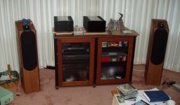
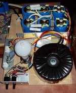
I built the power supplies on a piece of plywood so that I could experiment with different configurations and components before locking in the design and building a metal box. Due to space constraints, the amplifier chassis themselves had to be rather small, so hiding the power supplies in a cabinet was a reasonable solution to saving space. As a bonus I got to check off another of NP's top ten ways to improve an Aleph.
I used an RCRC filter for two reasons and I may extend it to RCRCRC with the final RC located inside the amplifier chassis. First of all, I had to burn about 10 volts in the power supply, since standard Plitron secondaries for 1000VA transformers are 25VAC or higher; so, adding some useless R before the first capacitor bank didn't hurt. The resistance before the first capacitor bank also reduces the peak charging current by about 17% according to PSU Designer. This, in turn, reduces the peak load on the transformers as well as the diode bridges. I am sure some of you are thinking, "just buy the correct secondary voltage." Maybe so. I had planned to purchase transformers from Victoria Magnetics (VM). However, at the time I needed to place the order, the transformers for my Class A test platform amplifiers were buzzing like a razor, so I settled on Plitron and saved about $150 for the pair. As it turns out, only one transformer was buzzing and it was due to a blown (shorted) diode in one of the bridges. About a month later, the whole bridge failed and after replacing it with a sturdier model, the transformers were as quiet as expected. As a result, I now have the Plitrons. They are working admirably. Perhaps I'll switch to electrostatically shielded VM transformers with 22 VAC secondaries at some point if I can think of a use for a pair of 1000VA, 2x25VAC toroids.
The soft start circuitry consists of a separate switch with a light bulb in series with the transformer primaries. After a couple of seconds, I switch on the bypass for full power. There is no thump in the speakers from either switch. As a bonus, the soft start switch also acts nicely as a reduced power mode, providing about +/-9 VDC to the amplifier rails and about 2.5 amps total bias with a 100W bulb. It seems ok for background listening up to a few watts, although I haven't used it much.
The power supply umbilicals are 12 gauge speaker wire that I had on hand. The supply returns are connected together in the amplifier on a solid copper wire stud soldered to the PCB.
With additional time and money, I plan to upgrade the components in the power supply, and perhaps even try a regulated supply along the lines of the Zen regulated supply.
Jeremy
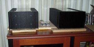
The Amplifier
Amplifier power is about 130 Watts into 8 ohms and 190 Watts into 4 ohms. The AC current gain is set to 63%, which seems to be the value chosen for the Pass Labs commercial offerings.
I can't say enough good things about Conrad Heatsinks, from which the bulk of the chassis are built. Their quality is top notch, service was excellent, and the prices were extremely competitive, even adding in shipping from Australia. Once everything was assembled the heatsinks did look a bit small. However, after firing up the system, they dissipate almost exactly as much power as the web site indicates. I had them drill and tap the heat sinks for the transistor mounts and for the assembly hardware. This was a small extravagence, but in the end well worth it. The heatsinks were delivered in perfect condition and I didn't have to risk breaking off a 6-32 tap or damaging them with further machining.
With the inputs disconnected and the -input jumper to ground removed, the amplifiers are almost dead quite into my 90dB (2.83V, 1m) efficiency B&W CDM7-NT speakers. Only with my ear against the tweeter grill, can I hear a faint hiss. With the -input jumpered to ground the hiss increases, and I can hear it a few inches away due to higher gain. Most of the time I can hear no 60Hz or 120Hz hum.
Don't forget to add your compensation capacitors. I initially left out the 5pF-10pF compensation capacitors across the feedback resistor. Measurements showed that output rang like a bell at about 200kHz with a square wave input. The gain also peaked handsomely at 160 kHz. Adding the 10 pF caps across the feedback resistor overdamped it slightly, but who needs a perfect square wave at 50 kHz.
I haven't listened to the system enough to really evaluate it, but my initial impressions are quite favorable comparing to my Rotel integrated amplifier, the ZV4/Aleph-30/AX-60 combination amp, and a gainclone. The Rotel integrated's pre-amp clearly degrades the sound, so I now use an attenuator directly off the CD player output. I can't drive the amplifier to the highest levels with this arrangement, so clearly the next project needs to be a pre-amp. After more tweaking and burning in, a trip to a local audiophile haven with the amplifier in tow is warranted.
The heat - oh, the heat - is almost exactly as calculated. I am running these babies at between +36 and +40C above ambient, depending on where you measure the temperature on the meat of the heat sinks. During the winter, that works out to about 60C, which is plenty toasty. I may have to throttle them back during the summer, since the ambient temperature could be 7 or 8 °C higher. The bridge diode mount is about 75C and the L bracket holding the first resistors in the PS are at 90C. That may require some attention.
I want to say a big thank you especially to GRollins for developing this idea and to all who contributed to the massive Aleph-X thread (and high-power AX threads) over the past couple of years. I started dreaming of this project back in 2002 when that particular thread was extremely active.
And finally, I wish to thank Nelson Pass for being so generous with his intellectual property and providing such an inspiration for those of us who want to get our hands dirty (or burned by soldering irons) and build top quality audio equipment. Even with Grey's schematic, I couldn't have done this without the Zen articles and the Aleph service manuals.
Jeremy

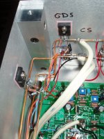
This is nice, the solid copper wires running like water pipes around the sides of the heat sinks…
/Hugo 🙂
/Hugo 🙂
Netlist said:Remember, there's the passdiy gallery.
/Hugo 🙂
There are a lot of tweaks and upgrades I'd like to do before calling this project complete, if there is ever such a thing with DIY - not to mention metal chassis for the power supplies.
Jeremy 😀
/beaming with pride
PS. In case it wasn't clear from the pictures, the power supplies are in the cabinet on the bottom right.
Netlist said:What are the big white wires you use for the supply rails?
They look massive from here.
/Hugo
The white wire inside the chassis is the same 12 gauge speaker wire I used for the power umbilical. It is OFHC copper wire with extremely fine strands, made by Tributaries. None of that matters, it is just what I had on hand. What does matter is that I had to set the wire strippers to the 10 gauge setting in order not to cut the wire. So, the 12 gauge label is probably misleading.
The bare, solid copper wires (top: plus rail, middle: minus rail, bottom: output) are 12 gauge from the local home center. I considered 6 gauge solid copper for the rails, but I wasn't sure my soldering iron could handle it.
Jeremy
Really nice work Kropf. I especially like the detail around the top of the amp for venting the FETs. That must have been a pain, either in the pocket or to diy.
Beautiful!
Like your solution for openings for better heat convection - I have something similar as an option with one of my project ...
Are those insulators kapton ones??
Like your solution for openings for better heat convection - I have something similar as an option with one of my project ...
Are those insulators kapton ones??
yldouright said:I especially like the detail around the top of the amp for venting the FETs. That must have been a pain, either in the pocket or to diy.
At work I have access to an old, but sizable, Bridgeport mill after hours. I knew I would be pushing the temperature limit, so every little bit helps. The single band on each side was the simpler of the two options. The other would have been the more traditional row of slots. Knowing my propensity to feed the mill too fast and get the measurement wrong, the fewer slots, the better.
Jeremy
Stabist said:Are those insulators kapton ones??
For the IRFP240s, I used Sil-pad 900 from Digikey. Between the differential pair on the PCB is a Kapton insulator.
I did a bench test comparing Kapton of difference thicknesses and the sil-pad, all dry, and the sil-pad won. The dry 1 mil kapton pad was very close (about 2 degrees C worse at 25 Watts). I didn't try the 1 mil kapton pad with thermal grease. Maybe that would have been better. Does anyone know, or have a guess?
I was hoping to use the Kapton, since for me it would have been a lot cheaper to cut them from some large sheets.
Jeremy
kropf said:A new Aleph-X has been born.
5 wire connection to the amplifier (12 gauge +/return, -/return, earth ground) terminated with Neutrik Speakon connectors, earth ground to amp chassis through thermistor
I also want to make my new PSU extern (to increase the lifetime of the caps). Can you elaborate a bit more on you wiring? Is +/-/gnd not enough?
Taco
- Status
- Not open for further replies.
- Home
- Amplifiers
- Pass Labs
- Another Aleph-X