hello community 🙂
I am in the mist of building a 12ax7 preamp that i could use with my fender twin reverb. I have completed my power supply schematic and ordered all the parts. I am now building the schematic (using TINA) for the main curcuit. I am trying to keep is nice and simple. I came here looking for some feedback on the following.
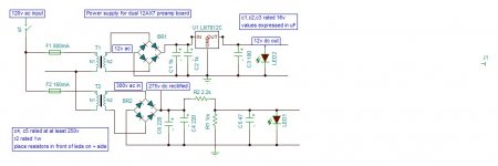
First- it wouldnt hurt to get some eyes on my power supply schematic. (see attached)
Second- well It got too late to finish the mainbaord schematic tonight, but i hope to have that posted tomarrow.
The power supply is there now. I will appreciate all feedback on the design.
Thanks for your time.
I am in the mist of building a 12ax7 preamp that i could use with my fender twin reverb. I have completed my power supply schematic and ordered all the parts. I am now building the schematic (using TINA) for the main curcuit. I am trying to keep is nice and simple. I came here looking for some feedback on the following.
First- it wouldnt hurt to get some eyes on my power supply schematic. (see attached)
Second- well It got too late to finish the mainbaord schematic tonight, but i hope to have that posted tomarrow.
The power supply is there now. I will appreciate all feedback on the design.
Thanks for your time.
Attachments
Just a quick question,
Are the AC voltages peak or RMS? I think the DC values may be low for some of the caps!
Think about off load.(warm up)
How many heaters are in the circuit I guess in series?
Think about start currents! The lm7812 dissipation may be an issue.
The cold resistance of the heaters is very low even in series.
Just for interest measure them cold DC resistance and work out the current.
Work out the Vd across the regulator and wattage.
Regards
M. Gregg
Last edited:
Second Miniwatt's comment. How do you get those voltages?
Why not split your dropping resistor and make a CRCRC supply? It will reduce your ripple.
The best way to look at both of these issues, is to download PSUD and do some sims. It's accurate and dead easy to use.
SY, I wondered the same. But he does specify a series resistor in a note.
Sheldon
Why not split your dropping resistor and make a CRCRC supply? It will reduce your ripple.
The best way to look at both of these issues, is to download PSUD and do some sims. It's accurate and dead easy to use.
SY, I wondered the same. But he does specify a series resistor in a note.
Sheldon
SY, I wondered the same. But he does specify a series resistor in a note.
Yeah, but that's pretty ambiguous. And if true, he'll be burning more current running the LED in the HV leg than used by the preamp circuit! Perhaps the LED would do better in the cathode of one of the 12AX7s?
Also, depending on the preamp circuit, it may or may not be a good idea to have the heater supply referenced to ground. It would also be a good idea to set it up so that common mode noise is not inadvertently injected through the heaters.
M greg- thanks for catching the cap v values error- that was supposed to be listed as 350v rating, not at 250v.
There will be 2 heaters in the circuit. I will have to give some thought on how to run them- I will be working on the schematic today/tomarrow.
The lm7812 issue and the cold heater resistance- Ill get back to that in a few days when parts arrive- Ill give it some thought.
Miniwatt- I am not sure about these values either- I have the transformer and when i tested it, it had an output of 300vac. But that was just the transformer, I havnt been able to measure these values activly. the 275vdc rectified- I had an extra bridge rectifier and wired it to the transformer and measured 275vdc from it. It is not the rectifier specified in the circuit. I understand your skeptisism of those listed values. I prob should have listed them in a note instead of lying them right in the schem.
SY- I hadnt given much thought to the LEDs. as soon as i read your comments i realized there has to be a better way to incorperate them- Ill work on them.
I had an extra bridge rectifier and wired it to the transformer and measured 275vdc from it. It is not the rectifier specified in the circuit.
Your measurement gave an erraneous result since there was no capacitor.
As soon as you add a filtering capacitor(s) after the rectifier the DC voltage will be some 350 to 400 volts. So you should use capacitors with 450 V rating.
Forget the LED at high voltage line. Instead use some other indicator having higher voltage rating and use proper series resistance.
In case of LED, some 99,5 % of the used power will dissipated in series resistor.
Quote:
I prob should have listed them in a note instead of lying them right in the schem.
Please put the values on the schematic notes are OK, however it helps so people do not over look information! 🙂
I think you will find that a capacitor on your DC after the rectifier will give you a different voltage. Probably higher than you have allowed for.
You may find that a soft start for the heaters will help! Lots of ways to do it , resistor with timed shorting contact, soft start regulators etc.
Hi Artosalo Same thoughts bet me to it!lol
Regards
M. Gregg
Last edited:
Yeah, but that's pretty ambiguous. And if true, he'll be burning more current running the LED in the HV leg than used by the preamp circuit! Perhaps the LED would do better in the cathode of one of the 12AX7s?
True enough. If not it the cathode, then just in series with the anode.
Sheldon
I attached an updated schematic
sheldon- I took your advice and placed another resistor between the caps (r3 on the new schem). I have got a copy of psu2 and am in the process of learning the software.
sy- giving thought to what you said about the heater referanced to ground- There is a note on the new schem about where i think you are refering to. eventually the 12vdc will be connected to pin 4 of the 12ax7. To this point i was going to connect pin 5 to ground, but , and correct me if i have misinterperited, now I am thinking of isolating the heater curcuit so that the heater power would not be referanced to ground. there are some notes on the schem. let me know what you think.
artosalo and mgregg- thanks for pointing out that the readings will be different and probally higher when caps are added to the circuit.
gregg im still looking at the lm7812. is part of the worry that the lm7812 will be asked to drop the V too much? the Vdrop on the datasheet is listed at 2V.
datasheet- http://www.fairchildsemi.com/ds/LM/LM7805.pdf
as for the LED, in series with the cathodes might be the way to go- Ill consider it when i design the main circuit.
last random question for today- does r1 serve a purpose? i forget why i put that there.
Attachments
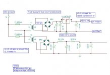
High voltage filter cap ratings.
The voltage rating of the high voltage filter caps (all 3) should be no less than 450 VDC. This rating is necessary as the rectified 300 VAC will be initially 1.414 times the AC RMS applied voltage of 300 VAC when the tubes are cold and have not get begun to draw current.
Resistor R1 is a bleeder resistor to provide a bleed off path for the filter caps upon shut down. I would suggest you lower this value to something on the order of 220k.
Mickeystan🙂
Hi,
Your values of voltage for the capacitors are low as stated in the above post. Also I would expect to see anything up to 19V dc on the caps on the heater supply after the rectifier. The 7812 will drop the voltage OK if you fit a heat sink. Run the heaters in series. you may need a soft start. I must admit I don't think 2000uF of Cap is going to make much of an impact on the heater supply ripple. I would be much higher then again its not my call! One other thing your heaters will be on the limits of under voltage 12V is not 12.6V. They will run you just need to be aware.
I would reference the heaters to .25 of HT supply connected in the middle of the heaters. However SY may have better choices for you!
You need to remember that the electrolytics should not be run at their maximum rating. If 200v was expected I would run 300v WKG at 300V I would run 450v WKG. Remember that if you apply over voltage to the caps they will "blow out" the vent and spray you with hot electrolyte.
Regards
M. Gregg
Last edited:
mickeystan- thanks for the info on the rectifier multiplier- I have changed my schem to reflect a need for 450v or higher caps. I also have re-seen my need for the bleed resistor (as to not keep hot caps in there after power down), thanks again. (i took your advice and lowered the 1m to a 220k ohm also)
Gregg- when you say to run the heaters in series: run the 2 tubes' heaters in series, run each individual tube heater sequence in series? to this point i was assuming both of these measures.
- i see how the 2k of caps might be low and also how there V ratings are definantly low. I have increased their ratings to 25v. Im thinking of increasing both of them to 4700uf for a total of 9400.
- your point about the 12 instead of 12.6 is well taken and also about the V ratings on caps.
Only thing i didnt understand was "to .25 of HT supply connected in the middle of the heaters". Im not familar with HT supply, or exatly what the middle of the heaters (the nutruel side of both heaters?)
Hi,
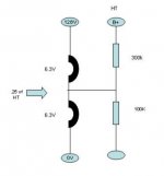
Try putting a diode in the ground leg (pointing away from the reg) of the 7812 see what output voltage you get.
If you lift the heater supply then you must remove the Gnd ref connection. This is just an example, you can use values for the circuit you need to keep the cathode and heater potential within a few volts.
You can keep the total value across the resistors the same and adjust values to suite the circuit you are using, see pic! (used in the aikido pre)
http://www.tubecad.com/2009/03/13/Aikido%20All%20in%20One.pdf
Again SY may have better ideas.
The capacitor values you refer to seem OK.
Regards
M. Gregg
Attachments
Last edited:
I have changed my schem to reflect a need for 450v or higher caps.
You can use PSUD to calculate the cap rating. Assume your transformer will have 5% higher secondary voltage with no load. Model the supply with a very low load (high value resistor load, or very low value current load). That will be the voltage reaches with the supply unloaded. Make sure your caps are at this value or higher.
your point about the 12 instead of 12.6 is well taken
Tubes are generally rated for +/- 10%, and that's conservative. So 12V is fine.
Only thing i didnt understand was "to .25 of HT supply connected in the middle of the heaters".
That's higher than necessary. You only need to lift the heaters to around 30V, relative to the cathode. Adjust the divider accordingly. And you might want to bypass the lower resistor with 10uf or so.
Sheldon
Last edited:
It will be helpful if you post the preamp schematic. That will enable (among other things) an evaluation of the best way to handle heater biasing. The power supply rejection of whatever topology you use is also critical in determining what the power supply actually has do do with respect to noise performance and the folks helping you here are sort of poking around in the dark.
PSUD2 reults showed max voltage to the caps in the 420v range and 16.5v for the heater caps at no load
Here is my preliminary pre-amp schematic.
already some extra notes- I have the heaters grounded to the main ground in this schematic, I might isolate them to the heater supply.
Here is my preliminary pre-amp schematic.
already some extra notes- I have the heaters grounded to the main ground in this schematic, I might isolate them to the heater supply.
Attachments
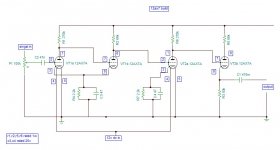
OK, glad I asked. There's a bunch of problems there, especially in the first three stages (think about what the grid and cathode voltages need to be) and we have to think about how to bias up the heaters (NOT grounded on one end!) to avoid challenging the maximum cathode-heater voltage spec.
- Status
- Not open for further replies.
- Home
- Amplifiers
- Tubes / Valves
- another 12ax7 preamp