hi shoog
90ma for bias
don t forget pa max=13 watt (26 watt for one 6080)
and 70% of pa max is better for tube life
what is your idle watt / triode
bye
90ma for bias
don t forget pa max=13 watt (26 watt for one 6080)
and 70% of pa max is better for tube life
what is your idle watt / triode
bye
jlsem said:"Please see RDH, pages 199-203."
I swiped this from another thread.
John
Or even;
http://www.audioxpress.com/resource/audioclass/ga300ac.pdf
and
http://www.audioxpress.com/resource/audioclass/ga400ac.pdf
Yves.
I am running 102mA against 100V plate voltage (taking the 30V bias). This gives me 100x0.1=10W or 20W per valve. It is a little less than one of the suggested operating points on the datasheet.
Shoog
Shoog
poobah said:You are talking about a method for PP analysis though, and I would like to learn more. I'm having trouble following why the impedance changes. You are talking about the effects of primaries driven simultaneously and a non superposition way of looking at the circuit?
If you look at class A PP as a balanced source then it might make sense. jlsem is right; it's not really that simple because rp varies with signal, so they don't make a truly balanced source. But it's a good simplification because it makes the analysis A LOT simpler.
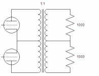
Anyway, consider a 1:1 PP transformer. Put 1000 ohm resistors across each half of the secondary. Since it's a 1:1 transformer the plate to plate load seen at the primary is 2000 ohms.
Now ask yourself the question: what load is seen across each half of the primary? Seems obvious by inspection that it must be 1000 ohms. It's a 1:1 transformer; the same load that's across each half of the secondary must appear across each half of the primary. That's 1/2 the plate to plate load.
If you drive only one side of the primary then you have a 1:2 voltage ratio which is a 1:4 impedance ratio. In that case the load seen would be 1/4 * 2000 ohms = 500 ohms. 1/4 plate to plate.
Incidentally, it's not hard to prove using conservation of energy. Since it's a 1:1 transformer the same currents and voltages must exist at both the primary and secondary. If the tubes each saw 1/4 the plate to plate load in class A then there would be a different amount of power going into the transformer than coming out. In fact, IIRC (it's been a while since I proved it to myself) you'll get different calculated powers depending on whether you use i*v, v^2/R, or i^2*R.
OTOH, when driving only one side (pure class B, if such a thing existed) then the power calculations work out ok at 1/4 plate to plate load.
-- Dave
Attachments
Thanks for all the information. Another jump on the learning curve.
Heres a related question. Assuming we stay in pure class A PP, what can we expect as max efficiency. Would it be 50%.
Shoog
Heres a related question. Assuming we stay in pure class A PP, what can we expect as max efficiency. Would it be 50%.
Shoog
I just wanted to correct some statements I have made.
The drive to the 6080's is 60Vpp which gives aplate output of 55Vpp.
The measurements I stated before were down to problems with I have with interpreting my scope. I apologies for any misunderstanding.
Shoog
The drive to the 6080's is 60Vpp which gives aplate output of 55Vpp.
The measurements I stated before were down to problems with I have with interpreting my scope. I apologies for any misunderstanding.
Shoog
Thanks Dave,
We were really talking apples and oranges... I didn't realize at first they we were talking about an "effective impedance" as a result of a compound analysis rather than a superposition type.
I'm itching to build a PP tube rig... if I can design or purchase OPT's that truely thrill me.
Funny you mention energy calcs... I am always using energy calcs to solve stuff. Crunch tricky stuff in a hurry and avoid all that Simulation and Laplace ****. One of these days I'll fork out for Mathematica and let it crunch instead... in the meantime, spreadsheets...
😉
We were really talking apples and oranges... I didn't realize at first they we were talking about an "effective impedance" as a result of a compound analysis rather than a superposition type.
Effective impedance is the same as the impedance seen by each tube in a push-pull scheme, which is the term I used in my post, for which I got hammered. Not apples and oranges.
Nice try,
John
- Status
- Not open for further replies.
- Home
- Amplifiers
- Tubes / Valves
- Anode loaded 6080 giving less than unity gain, Why??
