Hi all, slowly I am gathering parts for a new project to create a Headphone amplifier for my Beyerdynamic DT-770 250 ohms which has been lying around for years.
Since I like the simplicity of this design this is what I intend to build:
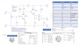
6AS7 Headphone Amplifier
A Single-Ended OTL Amplifier for Dynamic Headphones. – HeadWize Memorial
Now I have 2 grid chokes (Valab GC640-5 filter choke) and 2 anode chokes (Valab AP200-35 Anode) which also gather dust.
My question is if I can just replace R2 and R5 with chokes? I think in theory I could but anything I need to be aware of in this context?
Since I like the simplicity of this design this is what I intend to build:
6AS7 Headphone Amplifier
A Single-Ended OTL Amplifier for Dynamic Headphones. – HeadWize Memorial
Now I have 2 grid chokes (Valab GC640-5 filter choke) and 2 anode chokes (Valab AP200-35 Anode) which also gather dust.
My question is if I can just replace R2 and R5 with chokes? I think in theory I could but anything I need to be aware of in this context?
Attachments
Last edited:
"Valab GC640-5"
Possibly 640H choke, with undefined parasitic capacitance.
The 640H (on its own) about 80k at 20kHz, so it's very far from 1M.
Useful grid chokes has a few thousand Henry inductance and only few pF self capacitance.
Possibly 640H choke, with undefined parasitic capacitance.
The 640H (on its own) about 80k at 20kHz, so it's very far from 1M.
Useful grid chokes has a few thousand Henry inductance and only few pF self capacitance.
Thanks. I looked at specs for the grid choke: 20000 turn coils, generating 640H at 120Hz and over 2500H at 20Hz
In this case would it be a good idea?
In this case would it be a good idea?
Last edited:
I'm afraid it has to much capacitance, thus HF rolloff became early.
Try to measure it (handheld DVM unable to measure large inductor parameters).
The good grid chokes are rare, the Silk one is reliable, but costly:
SAC Thailand
Try to measure it (handheld DVM unable to measure large inductor parameters).
The good grid chokes are rare, the Silk one is reliable, but costly:
SAC Thailand
jev.....you can not change R2 with anode/plate choke without changing PS and doing so you need to be equipped with tube electronics knowledge. Changing R5 is little bit more complicated.
I request you to build the amp as it is and listen to it for 2/3 weeks at least. If you like it then only try to swap R2 and R5.
Regards
I request you to build the amp as it is and listen to it for 2/3 weeks at least. If you like it then only try to swap R2 and R5.
Regards
In the late 1930's and after the war, folks worked at removing as many distorting, bandwidth-reducing, phase-shifting, noise-coupling and expensive inductors as possible. But in this brave new world, a fashion among octogenarian Japanese coffee shop owners has become the new goal. Let's replace near perfect modern resistors and capacitors with something from the 1930's. preferably actually *made* in the 1930's, for real OG street cred.
Fashion is fun, but don't be a fashion victim.
All good fortune,
Chris
Fashion is fun, but don't be a fashion victim.
All good fortune,
Chris
Thanks all for your responses! Think I will build it as designed but will keep room in chassis for the grid choke. So I can swap and listen.
Cannot see any reason to use a grid choke for R1. It will most probably still make a sonic difference, but I see no technical arguments for a grid choke in this circuit.
R2 otoh is worth replacing with a choke but then R1 should be increased by the difference between R2 and choke resistance in order to keep the dc op point the same.
The cathode follower load is also worth replacing with a choke.
R2 otoh is worth replacing with a choke but then R1 should be increased by the difference between R2 and choke resistance in order to keep the dc op point the same.
The cathode follower load is also worth replacing with a choke.
As said above, especially by Chris Hornbeck, there's absolutely no need to replace modern, reliable and almost noiseless (compared to carbon comp) metal film resistors by chokes in this application. They'd introduce band pass behaviour, hence impact the overall performance. In addition, a choke in place of the 1st triode's plate resistor inevitably corrupts both triodes' operating points. In this case, the 47 k plate resistor has to be moved to R1's position at least.
I don't know what the designer was thinking when propagating chokes as direkt replacements for resistors, as in the BOM.
Best regards!
I don't know what the designer was thinking when propagating chokes as direkt replacements for resistors, as in the BOM.
Best regards!
So to correct this, the BOM is mine! not the designers 🙄I don't know what the designer was thinking when propagating chokes as direkt replacements for resistors, as in the BOM.
What a fun experiment!
That's the spirit! Leave space to substitute in the grid choke for the grid resistor on the 6922, space to put a choke in place of the anode resistor on the 6922 (making sure total DC resistance gives you the right voltage at the anode), and space to swap a choke in for the cathode resistor of the 6AS7 (again make sure DCR gives you the right bias point 🙂).
Then you can do your own experiments on your own headphones listening to your music to decide what works for you and what doesn't. Invite friends around to listen and give their views. Have fun with this! I would in your place!!
Think I will build it as designed but will keep room in chassis for the grid choke. So I can swap and listen.
That's the spirit! Leave space to substitute in the grid choke for the grid resistor on the 6922, space to put a choke in place of the anode resistor on the 6922 (making sure total DC resistance gives you the right voltage at the anode), and space to swap a choke in for the cathode resistor of the 6AS7 (again make sure DCR gives you the right bias point 🙂).
Then you can do your own experiments on your own headphones listening to your music to decide what works for you and what doesn't. Invite friends around to listen and give their views. Have fun with this! I would in your place!!
Yes! In my mind I am already building this. I have a chassis etc.
Now I do have anode and grid chokes in stock. But I have never seen chokes for the replacement of cathode resistor (btw also not sure if I want to try this) but what are the right chokes for this application?
Now I do have anode and grid chokes in stock. But I have never seen chokes for the replacement of cathode resistor (btw also not sure if I want to try this) but what are the right chokes for this application?
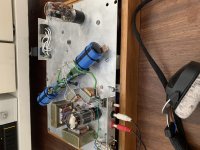
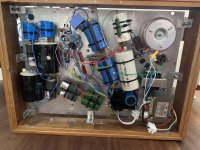
So it is working but with some hum. It sounds very good with very clear voices and even some stereo depth.
Some remarks:
Some remarks:
- 100uF in the output, but I have added extra 220uF bipolar for bass if I think I need
- Alu plate is decoupled with rubber grommets for vibration reductions
- Need to tidy up wiring so I hope this will reduce the hum
- With layout I have some long wires so hope it will be a fixable problem
- Need to add protection top and bottom. Probably I will use wood
- Really huge case for a headphone amp ..
- Seems like the chokes are doing their thing properly 🙂
Attachments
Last edited:
You might want to revise your heater wiring a bit. I don't think that CAT-5 wire is doing you any good. I would use tightly twisted pairs of #22 wire and get it as far away from the active devices as possible.
Very cool project my friend. When I built my OTL headphone amp, the #1 problem was fighting noise and hum. After all, the speakers are strapped to your head. It took some experimentation with wiring and frankly, just swapping power supply chokes, noting that bigger wasn't necessarily better. But it paid off, I ended up with a dead silent headphone amp that floors anyone that listens to it. I don't know I have direct recommendation, just it can be done and keep tweaking and you will get there and it is worth it.
Thanks 🙂 I will rebuild the amp now it has proven to work and to sound really good.
I will use the space below the alu plate for the power supply and build a new subplatform for the actual amp on top. This way I can keep signal paths short and keep supply leads seperate. Also I will use a seperate heater supply for the ECC88 and timed relays to mute outputs while powering up. In addition I have found two small power chokes I can use for the ECC88 part.
I will use the space below the alu plate for the power supply and build a new subplatform for the actual amp on top. This way I can keep signal paths short and keep supply leads seperate. Also I will use a seperate heater supply for the ECC88 and timed relays to mute outputs while powering up. In addition I have found two small power chokes I can use for the ECC88 part.
- Home
- Amplifiers
- Tubes / Valves
- Anode / grid choke good idea?