There must be a reason i can't find such an approach...
View attachment 857065
The reason could be a very simple one:
The conventional cathode coupled and your "anode coupled" circlotron might be substantially equivalent.
Consider the following "gedanken experiment" thought experiment:
Replace the hv power supplies by a short (what ac wise they are) and both circuits become identical.
Which means same input requirements, same output impedance, or not ?
Last edited:
oh, and it has been discussed in the literature, Broskie on tubecad.com, blog0340 calls it
quote:
The Other Circlotron
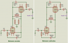
The Circlotron can be configured in an inverted fashion, wherein the output tubes appear below the load impedance.
http://www.tubecad.com/2012/12/29/Circlotron 4.png
Although it looks wrong, this inverted Circlotron works identically with the conventional Circlotron, delivering the same power output and distortion and output impedance.
unquote
The Other Circlotron
quote:
The Other Circlotron
The Circlotron can be configured in an inverted fashion, wherein the output tubes appear below the load impedance.
http://www.tubecad.com/2012/12/29/Circlotron 4.png
Although it looks wrong, this inverted Circlotron works identically with the conventional Circlotron, delivering the same power output and distortion and output impedance.
unquote
The Other Circlotron
But there is no difference with the output between cathodes, after all it's a series connection, tube-supply.
Without a coupling transformer you have to choose a reference point for the drive, try it.
Mona
What i had in mind is that driving the OPT from the plates would need a voltage swing divided by mu compared to cathode driven OTP.
I can't understand why plate is not affected by mu
Regarding reference point i am not sure what do you mean?
The reason could be a very simple one:
The conventional cathode coupled and your "anode coupled" circlotron might be substantially equivalent.
Consider the following "gedanken experiment" thought experiment:
Replace the hv power supplies by a short (what ac wise they are) and both circuits become identical.
Which means same input requirements, same output impedance, or not ?
''gedaken experiment'', 1st time heard of it, thanks for the info
As J.Broskie says both cathode or anode circlotron have same results so..
Same opt impedance and same opt power = same driving voltage for a given DF
But still can't understand why plate is not affected by mu
I will read beter the ''other circlotron'' article and i hope i'll find what i am missing
Last edited:
A voltage is between two points. Voltage swing between the grid and ???What i had in mind is that driving the OPT from the plates would need a voltage swing divided by mu compared to cathode driven OTP.
I can't understand why plate is not affected by mu
Regarding reference point i am not sure what do you mean?
There the reference point comes in, makes all the difference where it is.
Mona
What i had in mind is that driving the OPT from the plates would need a voltage swing divided by mu compared to cathode driven OTP.
I can't understand why plate is not affected by mu
Regarding reference point i am not sure what do you mean?
''gedaken experiment'', 1st time heard of it, thanks for the info
As J.Broskie says both cathode or anode circlotron have same results so..
Same opt impedance and same opt power = same driving voltage for a given DF
But still can't understand why plate is not affected by mu
I will read beter the ''other circlotron'' article and i hope i'll find what i am missing
Looking back from the load the driving impedance from a cathode is reduced by the factor (Mu + 1). So even for a simple load driven by a CF using a 6AS7 the driving impedance seen by the load is 1/3 of that from the plate.
Where do you see that difference ?Looking back from the load the driving impedance from a cathode is reduced by the factor (Mu + 1). So even for a simple load driven by a CF using a 6AS7 the driving impedance seen by the load is 1/3 of that from the plate.
The supply is a short circuit for AC, so I replace them by a simple connection.
The only change from cathode to anode is the centre tap = only the reference point for the input, halfway.No output current goes in or out the centre.
Mona
Attachments
")
Series applied voltage feedback works the same, whether the load is physically connected to the cathode or the anode. If the change in Va-k causes a change in Vk of the output tube with respect to the driver common, there is feedback.
So the question is, does Vk of the output tube still swing with respect to driver Gnd like when the load is connected to the cathodes (conventional circlotron)? Mona seems to be saying that it does and unless I'm missing something, I think I agree.
This seems like another way to get the same result.
You'll need a high swing driver unless you do something exotic like a floating transformer secondary driving the grids of the output tubes.
High swing drivers are doable. I played with a few triodes that are adequate when I built my Unity-Coupled amp. But the CCS-loaded pentode circuit I experimented with and pointed to upthread was a couple of orders of magnitude better.
- Status
- This old topic is closed. If you want to reopen this topic, contact a moderator using the "Report Post" button.
- Home
- Amplifiers
- Tubes / Valves
- Anode coupled circlotron with transformer