I have been messing with CCS anode loads (before xmas), and now in the new year, I have bothered to take measurements of its performance.
I have used a single BJT CCS, but quickly moved to a cascode pair of BJT (BC557 & ZTX558).
So...
What dynamic impedance constitutes a 'good' CCS anode load?
Having done some measurements and calculating the dynamic impedance, my result is 200k.
Now I know I could use DN2540 in cascode and probably better the results, but I'm waiting their delivery, and just wondered how "good" or "bad" a dynamic Z of 200k actually is.
What I know about CCS mostly comes from Merlin Blencowe -book- and Walt Jung -two first pdf attached. The third pdf provides useful information on how to select jfet for this job. Actually, the impedance of the CCS follows the general rule: it must be efficiently higher than the load it looks at. This is a few hundred ohm for a cathode but hundred thousands for an anode. So 200k for anode CCS doesn't seem good.
Attachments
Intuitively I'd say the 10:1 relation (acceptable loss of 10%) is still valid, so you'd use this 200K impedance up to an anode impedance of 20K.... just wondered how "good" or "bad" a dynamic Z of 200k actually is.[/I]
What dynamic impedance constitutes a 'good' CCS anode load?
1: CCS impedance is 'good or 'bad' when compared to the tube's own internal resistance. So if you're using an inherently low-impedance tube like the ECC88 / 6DJ8 then a >100kohm CCS might be considered 'good'. Whereas with a 12AX7 you might consider 'good' to be >1Meg. This is the first-principle answer.
2: But you may also have an additional external load. If your tube is trying to drive a 10k-ohm volume pot (for some reason, who knows) then a 'good' CCS might only need to be 100k ohms no matter what tube type you're using. After all, a tube with a 1Meg CCS, driving a 10k volume pot, sees 1M||10k = 9.9k. If you use a 100k CCS instead then it sees 100k||10k = 9.09k. Hardly any different -the pot dominates either way.
3: Variation in impedance with frequency. A CCS might have a really high impedance near DC, but drop at high frequencies due to stray capacitance or whatnot. Other CCS might work the other way around -what Broskie calls a 'compliant' CCS, or CCCS. Maybe constancy of impedance matters in your application. Maybe it matters to your sense of aesthetics. Maybe it doesn't. Now we're in the realm of finesse... but also cork sniffing...
You can see some of my CCS impedance measurements here:
Designing High-Fidelity Valve Preamps - Merlin Blencowe - Google Books
Long story short, a single DN2540 CCS will be good enough for 99% of tube applications.
Last edited:
Firstly thank you for your replies.
I have both of Merlin's preamp books, and also M. Jones 4th ed.
And I have seen the efforts and designs for CCS loads within (10m45s and DN2540 IIRC), I just wanted to get a "feel" for what constitutes good or bad performance regarding dynamic impedance, perhaps dynamic range is also relevant.
Magic bus, I should study the Jung pdf, as I dont have that reference, so thank you.
Merlin & Disco,
Thanks. Those statements help me to narrow down which criteria I am trying to meet.
I am using triode strapped pentodes, and I do not have a value for ra, yet; though I recall calculating a beam resistance at a single point, which was less than 20k.
I will test again for a range of voltages, to give me more confidence, and a measured ra I can work with. But it would seem I have a greater ratio dynZ:ra than 10:1. So that's not bad.
I certainly plan a volume pot between stages, so that point is very pertinent.
DN2540 on the way, so I'll test again once I have them.
Thanks again for the really very helpful replies.
Last edited:
So far, the criteria discussed deal with distortion performance. But there is also power supply noise rejection, which is 20dB at the 10:1 criterion but 40dB at 100:1, 60dB at 1000:1, etc. Which criterion is important depends on the particular circuit and application... :^)
Using low noise power supplies gives many more options for the amplifier circuits.
It is not always necessary to use ccs circuits, but yes, I do use them.
Just like 2 football teams, one with an uncreative play book and few options,
versus another team with a large and creative play book.
Quiet power supplies requires proper design, including special attention to ground loops,
reducing transient currents, and reducing the magnetic interference from the power transformer and choke that can couple to output and interstage transformers, including aluminum chassis, coils at right angles, and distance (fields fall off at the square of the distance).
Some improvement.
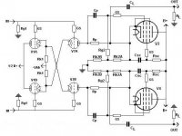
Today I experimented with the Veb voltage of the lower BJT in my anode CCS I read about ensuring the lower BJT is in saturation, while the upper BJT should operate in the linear range - so I posed that I could perhaps improve the operation by increasing the Veb voltage beyond the 1.8V provided by a red LED.
The voltage ref leg of the CCS passes about 4.5mA, so I added a resistance of 180R- increasing the Veb by about 0.8V to 2.6V. This is what I feel is a comfortable compromise to the max. Vebo of the ZTX558 (5V).
Lo and behold, now my input stage dynamic Z has increased ten fold to around 2M.
This low current input stage runs on about 0.7mA, and anoee volts are now rock solid.
No improvement on on the following stage
However, doing the same tweak has no effect on the following stage.
Or, perhaps the first tweak had jo effect and I just made a decimal place error.
I'll have to check that!
However, doing the same tweak has no effect on the following stage.
Or, perhaps the first tweak had jo effect and I just made a decimal place error.
I'll have to check that!
- Home
- Amplifiers
- Tubes / Valves
- Anode CCS load: Dynamic Impedance.