Niffy,
I understand what you are saying. As I said before, groove is a spiral so it will pull the cartridge towards center of record. But it is not skating we are talking about. There are a lot of factors to influence how strong skating force is, such as the material of record, music passage, etc. Spiral groove is one of them. If spiral groove is the reason to cause skating. Linear arms will have skating, too. Clearly, it is not correct. Skating is something inherits in LP playing back mechanism.
Jim
Hi Jim,
Following the spiral groove is not skating, that's just tracking. Skating is a sideways force created by the stylus drag and arm geometry. Skating is inevitable in any pivoted arm as far as I can tell.
Niffy
Following the spiral groove is not skating, that's just tracking. Skating is a sideways force created by the stylus drag and arm geometry. Skating is inevitable in any pivoted arm as far as I can tell.
Niffy
Trying to catch up.
Starting with my own in temperate hobgoblin remark. Jim's very elegant experiment and graphic indicate that tangency walks a very fine line to avoid skating. I still question how significant skating is among all the other forces effecting PLTs.
Jim - Thank you for doing that experiment and posting it. I think it's a major contribution to this thread.
Hiten - "100% perfection cannot be achieved. If we give weightage to tangential tracking, small skating force is a good compromise." Amen, brother.
Niffy - Even if I don't always agree with your assumptions and conclusions, I appreciate the clarity of expression. I've learned from your posts and even changed my mind once or twice. I've seen gross cantilever deflection in badly built or set up PLTs, but in more carefully built and set up ones, it disappears, at least to the eyeball level. I understand better now that deflection from whatever source can create offset and has to be accounted for.
RE your explanation at the bottom 1352: How much value would you give to stylus drag relative to that of the groove pushing the arm to the right? I have no idea how to quantify that.
Carlo - Re 1360: I don't quite understand what you mean by "direct" and "indirect" but I'm convinced that all arms rely primarily on the spiral groove force. My question is, if I'm right, what are the proportions between spiral and drag forces.
DD - I tried to figure out a way to turn Jim's moving cartridge, fixed pivot model into a PLT, but the results were incredibly messy and complicated. I'd like to see someone make that work. Frank's arm and my clone trace an ellipse, but use a moving pivot so the lines don't converge.
In Carlo's design, the string attachments can be positioned so the angle past the bearing is very close to 90 degrees and the bearing is tangent to a nearly straight line, which reduces the forward tension.
Repeating myself, if we can better analyze all the forces at play with PLTs, not just stylus drag, we'll better understand what's involved in these designs. As a for instance, a slight degree out of vertical in the lateral plane axis has consequences that can swamp the other forces. That's true for all tonearms, but it's especially true for PLTs and particularly multi-link versions.
Last edited:
Jim and Carlo,
Check the alignment details of the ellipse and the Thales circle. They're not the same. Back about two or three hundred pages, Jonathan Carr found that, for whatever reason, the Birch design based on the Thales circle, although very nearly tangent, is only truly null at three points. Jim's results are null at all points.
Again, I think there's a possibility Carlo's design results in an ellipse, which would be a very cool bonus.
Last edited:
Unfortunately for me I'm having to make all my post on my phone and do not have access to my main computer at the moment. If I did I would hopefully have been able to supply supporting diagrams and charts that explains why Carlo's arm skates. I can tell you that the level of skating decreases from the outer groove to inner and that the average is going to be similar to that of a 9" conventional pivoted arm (the skating force for the conventional pivoted varies less than for Carlos). If I had access to my computer I could make a graph showing how it varies with arm position. This would be useful in helping to design an antiskate mechanism that varies across the record to balance the skating force. Again I state that skating has nothing to do with the groove spiral. This is clearly demonstrated by Jim videos that show skating on a grooveless disc. Unfortunately I don't know how to show you with any more clarity what is so obvious to me. I just have to hope that the penny drops for those of you that it hasn't done so yet. I think that Jim will agree with me that sticking with linear trackers is easier. At least we know they have no skating. (don't tell DD that I polluted his thread with mention of the LT arm)
Niffy
Niffy
Niffy,
If and when you have access to your computer and can post the supporting evidence, I would love to see it.
I started building pivoting LTs because parallel LTs, as much as I liked the sound, made me crazy. Different strokes, etc.
If and when you have access to your computer and can post the supporting evidence, I would love to see it.
I started building pivoting LTs because parallel LTs, as much as I liked the sound, made me crazy. Different strokes, etc.
I think that Jim will agree with me that sticking with linear trackers is easier. At least we know they have no skating. (don't tell DD that I polluted his thread with mention of the LT arm)
Haha! If that's pollution then I might have poisoned everybody by now! Drawing examples and contrasting theories do not qualify as off topic. 🙂
================================================
Again, if Carlo's string+pulley guiding mechanism exhibits skating force, can we come up with something else that does not skate or skate less? I propose building a curved track (with a likely ellipse) to push+pull the carriage for elongation, sort of like the Schroeder LT's magnetic curved track. Low friction will not be easy though. In my own design (post#1275, 1277, 1283, 1288, 1290) the vertical arm is not that long, about 6", so the mass is reduced and that should help.
dear Direct driver
Since I do not love the strings (beautiful for instruments, less for tonearms, and for the same reason) i've previously explored many different options: gears, springs, cames, levers, wheels (left just magnetics to his master).-
What you say can be easy to build: the rail is a simple line, but is so steep! At first sight the side component of the force seems brutal.
The lever -in red- seemed more promising, but nearing to spindle the angles became problematic, multiplying friction and unwanted moments
carlo
Here a graph about the interesting Rex Johnston post#1294 geometry, compared with others
Attachments
Last edited:
Doug -
#1384 - I don't quite understand what you mean by "direct" and "indirect" but I'm convinced that all arms rely primarily on the spiral groove force. My question is, if I'm right, what are the proportions between spiral and drag forces.
Me too! Simply that direct means directly pulled from the stylus by side force and drag, indirectly trough strings, pulleys etc by side force and drag.
Found data on drag not for side force: maybe a fraction of drag for the first groove or with a frictionless pivot, but in our life at 2°, 3°, 4° etc without movement, sufficient to move a linear, or to pull the stylus out of groove. Too crude?
#1384 - Again, I think there's a possibility Carlo's design results in an ellipse, which would be a very cool bonus.
Where? Can't understand, sorry.
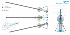
Surely i'll be boring, but I'll tell the story of how I came to the Syrinx - may be useful.
Everyone was doing the Thales (stringed, or with polygon) using the radius instead of the catheter: useful from a constructive point of view and for selling, but geometrically a nonsense. So I tried to use the catheter (reinventing the wheel).
Of course the catheter has to be stretched, that can be done converting angular motion into linear stretching, eg with two gears. Elliptical like in Birch?
After I made a graph with my old compass and paper (I understand better this way), and marked on the back the various elongations of the catheter. Surprise, the function of the angular movement of the catheter was a line (wow! in italian * °° !**** !, unrepeatable) so elongation could be achieved without gears or cames, using a simple string,
But where are the underhang errors coming from? Because the string is a chord and not an arc, and a chord is always shorter than the arc. But for small angles the difference is small. At the beginning the gadget was designed for a rotation from outer groove to the spindle (40 mm elongation 30 °) and error was > 5mm, then lowering it to the reading area (36 mm - 20 °) it was reduced to <3. We can still improve by choosing proper nullpoints, as old Baerwald did, maybe to a +-1 mm.
All here: for no error it's needed a curved string that could follow the arc ..... who sells?**
carlo
** or cleverer gadgets, of course
#1384 - I don't quite understand what you mean by "direct" and "indirect" but I'm convinced that all arms rely primarily on the spiral groove force. My question is, if I'm right, what are the proportions between spiral and drag forces.
Me too! Simply that direct means directly pulled from the stylus by side force and drag, indirectly trough strings, pulleys etc by side force and drag.
Found data on drag not for side force: maybe a fraction of drag for the first groove or with a frictionless pivot, but in our life at 2°, 3°, 4° etc without movement, sufficient to move a linear, or to pull the stylus out of groove. Too crude?
#1384 - Again, I think there's a possibility Carlo's design results in an ellipse, which would be a very cool bonus.
Where? Can't understand, sorry.
Surely i'll be boring, but I'll tell the story of how I came to the Syrinx - may be useful.
Everyone was doing the Thales (stringed, or with polygon) using the radius instead of the catheter: useful from a constructive point of view and for selling, but geometrically a nonsense. So I tried to use the catheter (reinventing the wheel).
Of course the catheter has to be stretched, that can be done converting angular motion into linear stretching, eg with two gears. Elliptical like in Birch?
After I made a graph with my old compass and paper (I understand better this way), and marked on the back the various elongations of the catheter. Surprise, the function of the angular movement of the catheter was a line (wow! in italian * °° !**** !, unrepeatable) so elongation could be achieved without gears or cames, using a simple string,
But where are the underhang errors coming from? Because the string is a chord and not an arc, and a chord is always shorter than the arc. But for small angles the difference is small. At the beginning the gadget was designed for a rotation from outer groove to the spindle (40 mm elongation 30 °) and error was > 5mm, then lowering it to the reading area (36 mm - 20 °) it was reduced to <3. We can still improve by choosing proper nullpoints, as old Baerwald did, maybe to a +-1 mm.
All here: for no error it's needed a curved string that could follow the arc ..... who sells?**
carlo
** or cleverer gadgets, of course
Last edited:
What you say can be easy to build: the rail is a simple line, but is so steep! At first sight the side component of the force seems brutal.
Here a graph about the interesting Rex Johnston post#1294 geometry, compared with others
Most of the guiding mechanisms you presented are BEHIND the pivot point, whose movement curve can be dramatic but what if the curved track is placed in FRONT of the pivot point as seen in Rex' graphic which is a variant of the Birch geometry. The Birch curve is closer to an arc instead of ellipse so it's easier to track on the rail. That's what I had in mind after abandoning the string approach.
Most of the guiding mechanisms you presented are BEHIND the pivot point, whose movement curve can be dramatic but what if the curved track is placed in FRONT of the pivot point as seen in Rex' graphic which is a variant of the Birch geometry. The Birch curve is closer to an arc instead of ellipse so it's easier to track on the rail. That's what I had in mind after abandoning the string approach.
My thinking is to minimise friction, using the stylus drag to pull the arm 'downhill' as it were.
Record eccentricity will always cause issues though. I was thinking along the lines of viscous damping of the guiding mechanism and some sort of horizontal compliance. This is aside from the basic geometry of the arm. On second thoughts that may not be a good idea.
Carlo,
Thank you for clarifying direct/indirect. That's a useful distinction.
Parallel LTs can have large masses, 60 gr or more, but the groove can move them just fine so the side force on the stylus must be significant.
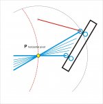
In the third photo, I've placed a circle over the red dots in your drawing. They don't quite fit. I think the red dots trace an ellipse. The circle you placed over Jim's ellipse doesn't quite fit. The circle/ellipse disagreement is a constant part of PLT design. There is something about the combination of circle arc around P and the fixed point B in the Birch geometry that creates very small intangencies across the LP - orders of magnitude less than an equivalent length pivoting arm, but still there. The secondary arm may not be the precise equivalent of the Thales radius and the difference shows as the stylus moves across the record.
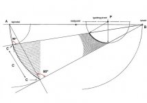
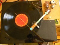
The pointer on the Birch arm - fourth photo - would not center over the spindle. Lots of English words like your Italian words. In the second photo I removed B, placed the pointer over the spindle center and traced a point behind the secondary arm. The magic ellipse appeared and has appeared all over the place since then. It's the symbol of tangent.
I think somehow when you and your compass discovered the line and you designed your indirect gadget, you designed an arm that is more tangent than the Birch.
I have some arc strings in my junk box. What size do you need? I could send you a couple.
Thank you for clarifying direct/indirect. That's a useful distinction.
Parallel LTs can have large masses, 60 gr or more, but the groove can move them just fine so the side force on the stylus must be significant.
In the third photo, I've placed a circle over the red dots in your drawing. They don't quite fit. I think the red dots trace an ellipse. The circle you placed over Jim's ellipse doesn't quite fit. The circle/ellipse disagreement is a constant part of PLT design. There is something about the combination of circle arc around P and the fixed point B in the Birch geometry that creates very small intangencies across the LP - orders of magnitude less than an equivalent length pivoting arm, but still there. The secondary arm may not be the precise equivalent of the Thales radius and the difference shows as the stylus moves across the record.
The pointer on the Birch arm - fourth photo - would not center over the spindle. Lots of English words like your Italian words. In the second photo I removed B, placed the pointer over the spindle center and traced a point behind the secondary arm. The magic ellipse appeared and has appeared all over the place since then. It's the symbol of tangent.
I think somehow when you and your compass discovered the line and you designed your indirect gadget, you designed an arm that is more tangent than the Birch.
I have some arc strings in my junk box. What size do you need? I could send you a couple.
Attachments

Rex,
If I understand your drawing correctly, try putting a magnet at the end of the stub arm, under or over, then put a ferris guide, either circle or ellipse, under or over the magnet, as appropriate, and see what happens. You'll have to account for some torsion at the main pivot from the magnet.
If I understand your drawing correctly, try putting a magnet at the end of the stub arm, under or over, then put a ferris guide, either circle or ellipse, under or over the magnet, as appropriate, and see what happens. You'll have to account for some torsion at the main pivot from the magnet.
Rex,
If I understand your drawing correctly, try putting a magnet at the end of the stub arm, under or over, then put a ferris guide, either circle or ellipse, under or over the magnet, as appropriate, and see what happens. You'll have to account for some torsion at the main pivot from the magnet.
Hmm, yes. Using a magnetic guide, which can be any curve i want, can ensure exact tangency. As drawn, this guide is so close to circular as to not be worth using. I might as well use another pivot point, as drawn by Carlo.
Last edited:
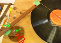
Hello Doug.
Kindly see attached picture that you have posted in #1394
Can unipivots be used in two places shown by green arrow. The moving pivot of arc piece can have counterweight to balance the cartridge holding arm. So We have extremely less friction, absolutely tight tolerance and when minor warp occurs the whole tonearm (The one with cartridge) moves vertically.
Regards.
Attachments
Dd
I was referring to your post 1368, but I see you went ahead. In this direction, and perhaps absolutely, I believe the Schroeder-Tuthill solution is unsurpassed
Doug
Since I do not have a mechanical cad (and I would not know how to use it) but just my old graphic program, I have to make certain checks just like on paper: with my eyes. So I often trace circles not to say that the points are above, but just to see how much they are away - Sorry if this has led off path.
So I did for the Jim chart - he and Dd talked about Thales and I wanted to see the differences. The only thing I have noted is that Jim had done a wonderful job thinking that test and in relation to working conditions. Results are remarkable.
So I did for mine. I'm led to believe that that curve is a cycloid (rotation + translation, like a wheel rolling on a surface). I've already asked 2wice about this.
However I'm just a diyer** and I think that Syrinx has worse problems than that: but I want to try it the best I can, and if it will turn smoothly and play acceptably I'll be happy the same. I'm not a skate taliban (just a bit for azimuth)
Carlo
archery: really they mantain an arc shape? wow! ****!°°**!
** I have a son working at CERN, but if I talk about this stuff he looks at me with a little smile of compassion.


- Home
- Source & Line
- Analogue Source
- Angling for 90° - tangential pivot tonearms