Hey all.
Anyone tried this one?
http://www.audiodesignguide.com/my/pp3.html
Worth building? The specs are pretty much what I'm looking for. A simple KT88 PP with about 20W output.
Anyone tried this one?
http://www.audiodesignguide.com/my/pp3.html
Worth building? The specs are pretty much what I'm looking for. A simple KT88 PP with about 20W output.
Sorry, I have not tried this design.
But I love the simplistic beauty of the circuit. 🙂
There are a couple of related threads on the K&K (Lundahl) forum:
http://www.audioasylum.com/cgi/t.mpl?f=kandk&m=4663
http://www.audioasylum.com/cgi/t.mpl?f=kandk&m=1133
SveinB
But I love the simplistic beauty of the circuit. 🙂
There are a couple of related threads on the K&K (Lundahl) forum:
http://www.audioasylum.com/cgi/t.mpl?f=kandk&m=4663
http://www.audioasylum.com/cgi/t.mpl?f=kandk&m=1133
SveinB
It's a classical 1930'th design. Results depend very much on an interstage transformer's selection.
Results depend very much also on the quality, condition and age of the tubes, since there is no NFB to normalize them.
Experience tells me that interstage phase splitting sounds very good and it is well worth the investment in suitable quality iron (these can stay with you for multiple builds).
However the choice of KT88 as the output devices seems quite a poor one. Damping factor will be poor because of the relatively high rp of the KT88, even when triode strapped. If you can live with less power some type of high powered triode would be a much better option. Even a 300B would be a good choice.
Shoog
Very similar to Sun Audio SV-KT88PE.
Manufacturer web site: http://www2.big.or.jp/~sunaudio/sv/svkt88pe_e.html
Schematic:
http://www.meta-gizmo.com/Tri/sunschematic.html
(actually, this is for the SV-300B MKII, but the schematic is very similar for the KT88 version).
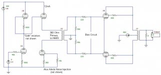
Attached is a simplified schematic of my current project, using 6CG7 valves. Not shown are Aikido noise cancellation capacitor/resistor divider, "safety" resistors in the Aikido circuit, and the grid bias for the KT88 output valves. Also not shown is ultra-linear taps for the output stage (if desired). I'll probably build this as a Class-AB1, with about 50mA idle (each) on the output valves.
The LL1660S has about 360 Ohms of primary winding resistance, which means the transformer winding also serves as the cathode bias resistor to Aikido valve V2B (upper valve).
Manufacturer web site: http://www2.big.or.jp/~sunaudio/sv/svkt88pe_e.html
Schematic:
http://www.meta-gizmo.com/Tri/sunschematic.html
(actually, this is for the SV-300B MKII, but the schematic is very similar for the KT88 version).
Attached is a simplified schematic of my current project, using 6CG7 valves. Not shown are Aikido noise cancellation capacitor/resistor divider, "safety" resistors in the Aikido circuit, and the grid bias for the KT88 output valves. Also not shown is ultra-linear taps for the output stage (if desired). I'll probably build this as a Class-AB1, with about 50mA idle (each) on the output valves.
The LL1660S has about 360 Ohms of primary winding resistance, which means the transformer winding also serves as the cathode bias resistor to Aikido valve V2B (upper valve).
Attachments
Shoog said:However the choice of KT88 as the output devices seems quite a poor one. Damping factor will be poor because of the relatively high rp of the KT88, even when triode strapped. Shoog
What would be a ralistic output impedance of a triode strapped PP output stage with KT88 (or EL34) ?
SveinB
Kashmire said:
Attached is a simplified schematic of my current project, using 6CG7 valves. Not shown are Aikido noise cancellation capacitor/resistor divider, "safety" resistors in the Aikido circuit, and the grid bias for the KT88 output valves. Also not shown is ultra-linear taps for the output stage (if desired). I'll probably build this as a Class-AB1, with about 50mA idle (each) on the output valves.
The LL1660S has about 360 Ohms of primary winding resistance, which means the transformer winding also serves as the cathode bias resistor to Aikido valve V2B (upper valve).
No comments.

Kashmire said:Cryptic response. Elaborate.
You loose gain such a way and increase impact of oddnesses of an interstage transformer.
Try to shunt a CCS in cathode of the cathode follower by a capacitor, you'll be surprised.
Thank you for clarifying your position on this matter.
Bypassing the entire CCS (V2A, bottom valve) with a capacitor certainly rescued a lot of gain.
Bypassing just the 360 Ohm cathode resistor of the CCS (V2A, bottom valve) with a capacitor is also helpful, but not as much.
I'll do further study to understand the tradeoffs.
The entire CCS can be replaced by a single large-value resistor (about 16300 Ohms) that mimics a CCS. Again, bypassing this resistor with a capacitor looks recommended.
Since I am using dual-triode envelopes, I may as well use an active CCS instead of a resistor.
That leaves the question of choosing the bypass point - either bypassing 150VDC from the bottom of the interstage transformer to ground, or 3VDC from the CCS cathode to ground.
Also, I noticed the interstage transformer destroys the symmetry of the Aikido noise-reduction philosophy, so the noise cancellation effect doesn't work in this arrangement.
Kashmire said:Thank you for clarifying your position on this matter.
Bypassing the entire CCS (V2A, bottom valve) with a capacitor certainly rescued a lot of gain.
Bypassing just the 360 Ohm cathode resistor of the CCS (V2A, bottom valve) with a capacitor is also helpful, but not as much.
I'll do further study to understand the tradeoffs.
The entire CCS can be replaced by a single large-value resistor (about 16300 Ohms) that mimics a CCS. Again, bypassing this resistor with a capacitor looks recommended.
Since I am using dual-triode envelopes, I may as well use an active CCS instead of a resistor.
That leaves the question of choosing the bypass point - either bypassing 150VDC from the bottom of the interstage transformer to ground, or 3VDC from the CCS cathode to ground.
Also, I noticed the interstage transformer destroys the symmetry of the Aikido noise-reduction philosophy, so the noise cancellation effect doesn't work in this arrangement.
You may parallel both triodes for a cathode follower, and use a resistor bypassed by a cap instead of the CCS.
edit: extra gain may be reduced by a resistor from output to cathode of the first bottom triode (X4)
If the amp starts oscillating reverse polarity of the output winding.
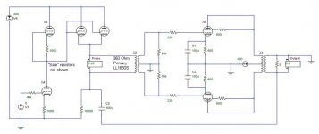
Here's what this is evolving into. See attached schematic. Maybe this form of GFB is more palatable?
I lament the fact that the Aikido noise cancellation is lost. Noise on the driver stage PSU is efficiently translated into the output stage, so some of the original beauty is lost.
[cathode bias is shown on output stage for simplicity]
I lament the fact that the Aikido noise cancellation is lost. Noise on the driver stage PSU is efficiently translated into the output stage, so some of the original beauty is lost.
[cathode bias is shown on output stage for simplicity]
Attachments
Kashmire said:Here's what this is evolving into. See attached schematic. Maybe this form of GFB is more palatable?
I lament the fact that the Aikido noise cancellation is lost. Noise on the driver stage PSU is efficiently translated into the output stage, so some of the original beauty is lost.
[cathode bias is shown on output stage for simplicity]
Looks interesting, though it is not a GNFB, it is a local NFB around an output stage only.
What noise cancellation do you mean?
blacklight said:Hey all.
Anyone tried this one?
http://www.audiodesignguide.com/my/pp3.html
Worth building? The specs are pretty much what I'm looking for. A simple KT88 PP with about 20W output.
With this circuit, a matched quad KT88 is perfect.
What happens when the tubes aged and you don't have matched quad anymore? How is the current through the tubes balanced?
I built a similar PP KT88 with cathode bias with no provision to balance the output tubes and I am worried when my KT88 are no long matched.
Kashmire said:Here's what this is evolving into. See attached schematic. Maybe this form of GFB is more palatable?
I lament the fact that the Aikido noise cancellation is lost. Noise on the driver stage PSU is efficiently translated into the output stage, so some of the original beauty is lost.
[cathode bias is shown on output stage for simplicity]
Reconfigure as a standard aikido and use parafeed style arrangement to drive the transformer. Connect one side of the transformer primary to the node between the CF cathode and the CCS plate. Place the blocking cap on the low side of the transformer primary. This will allow you to use the psu noise canceling circuitry in the aikido design.
With this circuit, a matched quad KT88 is perfect.
What happens when the tubes aged and you don't have matched quad anymore? How is the current through the tubes balanced?
I built a similar PP KT88 with cathode bias with no provision to balance the output tubes and I am worried when my KT88 are no long matched.
In your situation I would be very concerned about this issue.
There are three ways of overcoming this;
Use a simple Ring of Two or LM317 CCS in the tail of each KT88. This may not be acceptable to you because it requires a cap in the signal path and you lose some voltage over the CCS.
Use a voltage divider trim pot to adjust each grid individually off your bias supply. The will require regular adjustment.
Alternatively a trim pot can be used to adjust a self bias network, but again you will need to put either a resistor or a CCS in the shared tail. No cap though but adjustment will be a regular chore.
There are some sophisticated bias servos on the Tubecad site, but not for the beginner I feel, and they eat voltage.
I know you are unhappy with your bass response and this is at least partly due to your lack of feedback. Without feedback your bass will inevitably be substandard. Think about moving your interstage transformer to the front end and driving a LTP into the KT88 grids. This will allow you to wrap a gNFB around the amp and back to the LTP. Alternatively you can easily introduce Plate to Plate feedback. Your frequency response should improve at both ends, your phase splitting should be perfect (better than the interstage by itself) and you should be able to eliminate the interstage parafeed cap. Most of the advantages of the interstage transformer are preserved. All for the price of one extra triode. I am thinking of doing the same to my 6080 PP amp, but my issues are much less serious due to the lower output impedance of the 6080's.
Another possability is to try to tune the parafeed cap to introduce a bass resonance which will artificially compensate for the bass fall off you are experiencing. I found something around 1-2uf hits the mark though this will depend on the particular brand of interstage you are using.
Think about it.
Shoog
I have an amplifier with a design similar to this one here:
http://www.diyparadiso.com/boully1.htm
Like Andrea Ciuffoli's design it's a PP with an interstage for the phase splitting but with the addition of negative bias for the output tubes, so it's easy to get the tubes matched.
As for the interstage for phase splitting: it sounds superb!
Before I had a concertina phase splitter and I prefer much more the interstage !
Regards,
Danny
Re: Re: Andrea Ciuffoli's KT88 PP
The rp of Kt88 triode connected is around 700 ohms, a stones throw from that of a 2A3 or 300B. (I used to build amplifiers with triode connected KT88.)
Individual cathode resistors do a fairly good job of keeping the idle currents matched between the various output tubes, however I don't like it because of the need for a questionable quality cathode bypass cap., and this has a audible effect on bass quality and also results in rising output impedance at low frequencies. I don't think it helps much with dynamic as opposed to static matching, but then neither does fixed bias. The cure for that is to use well matched (multi-point) and properly aged tubes.
I don't use global feedback at all in any of my designs, and my 300B PP amplifier is able to deliver 25W of output power all the way down to 10Hz. Damping factor is low but consistent until you run out of primary inductance at the low end at which point thd starts to go up and coupling to the output falls off.
You need a high quality interstage transformer with plenty of primary inductance for good low frequency performance - the minimum amount required is dictated by the driving source impedance and your desired LF cutoff.. (Watch out for subsonic resonances as well particularly in parafeed arrangements.) At the other end (HF) you need a design that has both low leakage inductance and relatively low stray capacitance.
alexg said:
With this circuit, a matched quad KT88 is perfect.
What happens when the tubes aged and you don't have matched quad anymore? How is the current through the tubes balanced?
I built a similar PP KT88 with cathode bias with no provision to balance the output tubes and I am worried when my KT88 are no long matched.
The rp of Kt88 triode connected is around 700 ohms, a stones throw from that of a 2A3 or 300B. (I used to build amplifiers with triode connected KT88.)
Individual cathode resistors do a fairly good job of keeping the idle currents matched between the various output tubes, however I don't like it because of the need for a questionable quality cathode bypass cap., and this has a audible effect on bass quality and also results in rising output impedance at low frequencies. I don't think it helps much with dynamic as opposed to static matching, but then neither does fixed bias. The cure for that is to use well matched (multi-point) and properly aged tubes.
I don't use global feedback at all in any of my designs, and my 300B PP amplifier is able to deliver 25W of output power all the way down to 10Hz. Damping factor is low but consistent until you run out of primary inductance at the low end at which point thd starts to go up and coupling to the output falls off.
You need a high quality interstage transformer with plenty of primary inductance for good low frequency performance - the minimum amount required is dictated by the driving source impedance and your desired LF cutoff.. (Watch out for subsonic resonances as well particularly in parafeed arrangements.) At the other end (HF) you need a design that has both low leakage inductance and relatively low stray capacitance.
Shoog said:
......
I know you are unhappy with your bass response and this is at least partly due to your lack of feedback. Without feedback your bass will inevitably be substandard. Think about moving your interstage transformer to the front end and driving a LTP into the KT88 grids. This will allow you to wrap a gNFB around the amp and back to the LTP. Alternatively you can easily introduce Plate to Plate feedback. Your frequency response should improve at both ends, your phase splitting should be perfect (better than the interstage by itself) and you should be able to eliminate the interstage parafeed cap. Most of the advantages of the interstage transformer are preserved. All for the price of one extra triode. I am thinking of doing the same to my 6080 PP amp, but my issues are much less serious due to the lower output impedance of the 6080's.
Another possability is to try to tune the parafeed cap to introduce a bass resonance which will artificially compensate for the bass fall off you are experiencing. I found something around 1-2uf hits the mark though this will depend on the particular brand of interstage you are using.
Think about it.
Shoog
Hi Shoog,
I am using an autoformer (center tapped choke) as phase inverter, which I don't think I can move in front just like an interstage.
With the autoformer as phase inverter, I cannot use a plate to plate feedback, or can I?
I will try to introduce feedback and see what happens.
BTW, I added more current on the paralleled 6n1p driver and somehow the bass improved, I might bumped it up a bit (I am at 8ma per triode on the 6n1p, before it was at 6ma) to about 10 to 12ma per triode (6n1p I think is rated at 20ma max).
Thanks.
- Status
- Not open for further replies.
- Home
- Amplifiers
- Tubes / Valves
- Andrea Ciuffoli's KT88 PP