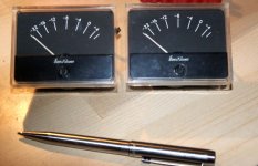
So , I have some VU-meters left over from an old Midas console. There are actually two types: one is the original with a large white 4"x3" scale ranging from -20 to +3 (usually standard on all VU's), and below the scale it says "ÖVU=1·228V=7500Ω.@1000~".
The other one is a replacement VU with a smaller black 2.5" x 2.5" scale ranging from -20 to +5 (?), nothing printed below that, and on the back are 4 (I'd say germanium) diodes in a rectifying bridge configuration.
Now, how do I / should I connect these in order to build a nice 2-channel VU-meter with balanced in/out connectors in order to monitor the input level of an old Quad-Eight (Q8) preamp that lacks of VU's?
I imagine that I have to build a special circuit for that. Any hints on some schematics would be great.
Thanks in advance,
Phantombox
So , I have some VU-meters left over from an old Midas console. There are actually two types: one is the original with a large white 4"x3" scale ranging from -20 to +3 (usually standard on all VU's), and below the scale it says "ÖVU=1·228V=7500Ω.@1000~".
The other one is a replacement VU with a smaller black 2.5" x 2.5" scale ranging from -20 to +5 (?), nothing printed below that, and on the back are 4 (I'd say germanium) diodes in a rectifying bridge configuration.
Now, how do I / should I connect these in order to build a nice 2-channel VU-meter with balanced in/out connectors in order to monitor the input level of an old Quad-Eight (Q8) preamp that lacks of VU's?
I imagine that I have to build a special circuit for that. Any hints on some schematics would be great.
Thanks in advance,
Phantombox
Sounds like it's calibrated for +4dBu which might not be sensitive enough. An amplifier / attenuator will allow you to tweak it to where you thnik it's good. There is no _right_ (or wrong) answer since the whole concept of the dB is based on ratios. You might want to add a coupling capacitor to block any potential DC which would alter the readings.
In broadcast in the US it's very common to have the '0' reference operating level at +4 dBu, AKA 1.228 V rms. It's been a LONG time since I saw any broadcst facility actually terminate their 600 lines at 600 ohms which would be +4dBm.
In my opinion VU meters with 23dB scale range are pretty much useless for setting anything other than continuous tones. With analog tape machines it takes quite a while to realize that jingling a ring of keys in front of the mic should be set at -15 to -20 because the ballistics of the meter will not show you the peaks which in fact are up near 0. Peak reading meters with controlled decay are more suitable for actual audio.
G²
Interesting, I just picked up a really nice pair of VU meters that were on special at a local electronics shop. I plan to do this project with mine (link below).
Project 128
I use a fair few ESP boards and actually have one of his balanced receiver boards handy. Will let you know how I go.
col.
Project 128
I use a fair few ESP boards and actually have one of his balanced receiver boards handy. Will let you know how I go.
col.
In my opinion VU meters with 23dB scale range are pretty much useless for setting anything other than continuous tones. ... Peak reading meters with controlled decay are more suitable for actual audio.
In my opion, depends what your trying to do. You want peak meters recording digitally, you want VU for recording on anlogue tape, and you want both when your mixing.
VU meter - Wikipedia, the free encyclopedia
"A VU meter is often included in audio equipment to display a signal level in Volume Units; the device is sometimes also called volume indicator (VI).
It is intentionally a "slow" measurement, averaging out peaks and troughs of short duration to reflect the perceived loudness of the material."
A VU is usually a little better at showing relitive RMS power levels (highly influenced by program material) but niether VU or peak meters are true power meters.
I think a VU meter is what you want for pre amp input, although with the way most music these days is limited to near death a peak and a VU will look almost identical.
Actually it was an analog tape recording that was the problem. A commercial audio house had recorded a 'ding' from a triangle that was used in a TV commercial. They set the audio level so that the ding peaked at 0 on the VU meters. This was about 20dB more than it should have been and it sounded aweful which was why they asked me to check out what was wrong. I stand by my statement that VU meters are only good for test tones.
Check out the metering in Adobe Audition. That's how it should be done. Even a second grader can get that right.
G²
I have these, wired with an Alps Pot...I can just set them to whatever level that I am listening to...And they work Great...Still have to find that Nice cigar box to put them in...
http://www.diyaudio.com/forums/analog-line-level/161274-diy-dancing-needle-box.html
http://www.diyaudio.com/forums/analog-line-level/161274-diy-dancing-needle-box.html
ctually it was an analog tape recording that was the problem. A commercial audio house had recorded a 'ding' from a triangle that was used in a TV commercial. They set the audio level so that the ding peaked at 0 on the VU meters. This was about 20dB more than it should have been and it sounded aweful which was why they asked me to check out what was wrong. I stand by my statement that VU meters are only good for test tones
Sure you can always find an example that is unusual ( and are you sure the problem wasnt somewhere else, theres a dozen places to ruin the sound with hard clipping before it hit the tape and its built in soft peak limiting (which is the reason some people still prefer analogue tape for some sounds, like drums)). Peak meters have been available for 40 years, but they where never put in mixers or tape machines for a reason; there not appropriate. Most music is no where near as peaky as some sounds (like percusive hits (triangle) or keys jingling ) your example is not very good. Try recording a vocal track to analogue tape with a peak meter. Check out a Dorrough meter, the standard in recording studios (not software). I mixed in front of a pair for over 10 years.
Last edited:
wow.. those Dorrough meters are really nice. I like the demo on the home page too, if gives a good example of how to read the levels in relation to the music being played. Feel inspired to get cracking on my VU project now.
col 🙂
col 🙂
those Dorrough meters are really nice
Nice and expensive, hey, theres a challenging DIY project!
Sure you can always find an example that is unusual ( and are you sure the problem wasnt somewhere else, theres a dozen places to ruin the sound with hard clipping before it hit the tape and its built in soft peak limiting (which is the reason some people still prefer analogue tape for some sounds, like drums)). Peak meters have been available for 40 years, but they where never put in mixers or tape machines for a reason; there not appropriate. Most music is no where near as peaky as some sounds (like percusive hits (triangle) or keys jingling ) your example is not very good. Try recording a vocal track to analogue tape with a peak meter. Check out a Dorrough meter, the standard in recording studios (not software). I mixed in front of a pair for over 10 years.
It wasn't clipped in the classic sense of snipping off the tops and bottoms of the signal. Analog tape doesn't really clip. Its starts squashing the signal as you overload it. Peak reading meters are certainly appropriate for any recording device where you want the levels correct. Metering that you have to 'interpret' based on program content will always get some people in trouble level wise. Folks have a tendency to place the meters average in the middle of the scale. With a 23 dB range meter, that's mighty narrow combined with program material that typically reads low is a recipe for trouble.
Don't believe me? Get a scope on your VU meter equipped gear and set a test tone to 0 on the meter and 6 divisions on the scope. Now change the program material to keys jingling (something you can easily do at home), set the peaks to the same level on the scope and check the VU meter. It will be 15 to 20dB low. Worse, some other program material will be much closer to the same. Solo flute or a pipe organ flute stop will be very close meaning you have to 'interpret' the readings. Try all sorts of different program and you'll find it's all over the map. I think true VU meters are close to useless for program audio if you want it right - but the test tones will be perfect.
The 46 dB peak reading meters on my old Nakamichi cassette are much better but the 60 dB range peak metering on the Sony digital processor is better yet and the 96dB range in Adobe Audition with lagging peak levels is about as good as it gets meaning it's virtually the same as the scope all the time. In fact it's better than the scope as you might have blinked and missed a peak but the lagging peak reading will catch it.
Broadcast machines have had peak meters (sometimes selectable peak / VU) for 30 years. Any place I've worked with switchable meters have ALWAYS been set to peak.
G²
This is how 1mA meters work when run thru a 10k Alps from the Speaker Posts..
YouTube - Too Old2.mp4
YouTube - Too Old2.mp4
I still have a pair of these ..
From a discrete PPM (Peak Program Meter) built to BBC standards with a Dolby B processor on my Revox 15" dual track.
1970's - thank you Wireless World!
These have special ballistics which are critically damped and have to be driven with a fast rise-time / slow fall-time meter driver.
I don'r suppose I shall ever get round to using these again - are they worth anything to anyone?
Cliff
Attachments
Now I built a circuit based on the ESP project 128. Instead of 2 TL072's I use 1 TL074, and as power supply I use a regulated single rail unit with virtual ground and set it at +24V (+12/-12V). In theory, voltage should not affect the output signal but it does. The higher I set the total voltage the more does the needle swing. I'm almost certain that I made a mistake but cannot figure out where it is.
My last project was a PIAA phono preamp with a TL074 and a 12V wallwart and virtual ground and it works just fine, so I think the PS is OK.
Any suggestions?
My last project was a PIAA phono preamp with a TL074 and a 12V wallwart and virtual ground and it works just fine, so I think the PS is OK.
Any suggestions?
Any suggestions?
Yes! Post a schematic!!
You have something V+ referred rather than ground referred - but how do you expect anyone to help without a drawing?
Here's the schematic of the VU driver: Project 128 (figures 3 and 4. See the 2nd reply to my post by Col from AustrAlia) and here is my power supply: http://kitsrus.com/pdf/k124.pdf (end of page 2, acts s a "wall wart"), followed by a dividing circuit with two 220uF capacitors and two 4.7k resistors (that's the virtual ground).
- Status
- Not open for further replies.
- Home
- Source & Line
- Analog Line Level
- analogue VU-meter